
clewsy
A work-in-progress
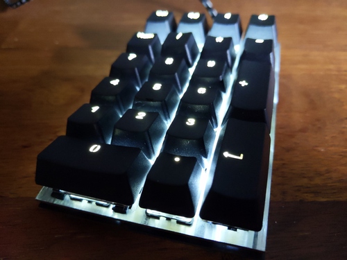
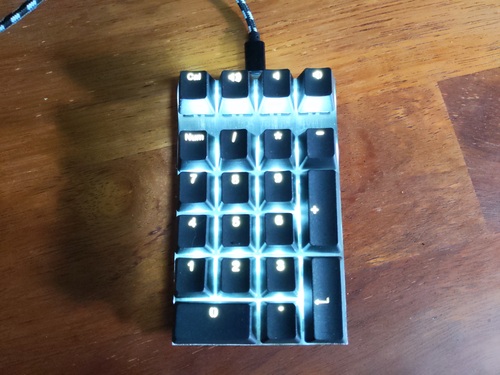
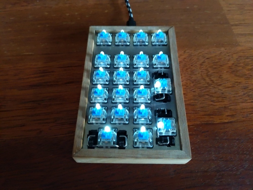
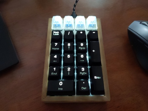
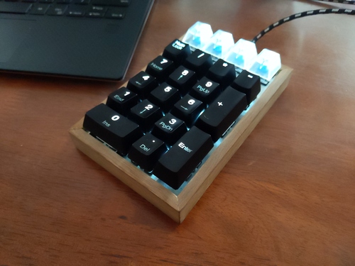
jank is just another keypad. Specifically it's a 21-key usb numeric keypad. I wanted one for use with my laptop. Sure it would have cost a lot less to just buy one, but... (insert justification here when you think of one). jank is open-source with all the code and CAD files available at GitLab. The main features of this keypad include:
I previously completed a similar but simpler project (macr0) which served as an experiment to prepare for this project. macr0 was effectively a trial so that I could get my head around a few concepts (key matrixing, LED boost controllers, configurable macros with the HID protocol). As such, development for jank went a lot faster since I re-used code from macr0 with minimal changes.
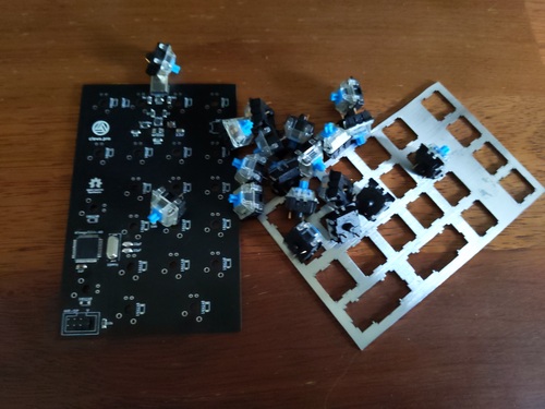
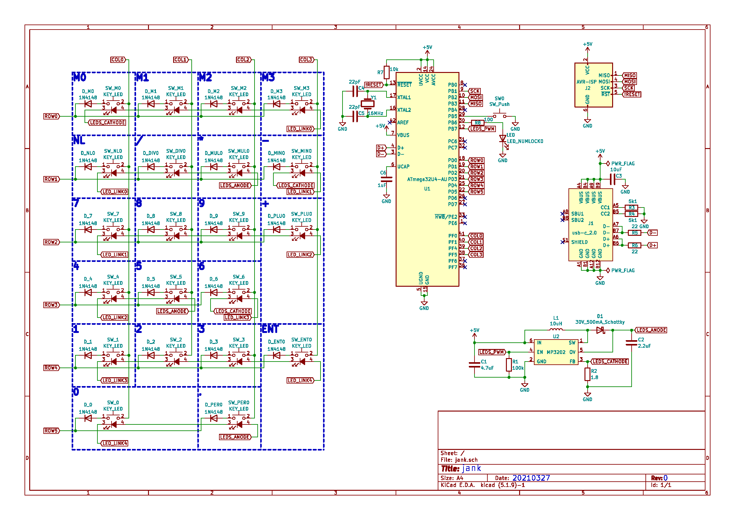
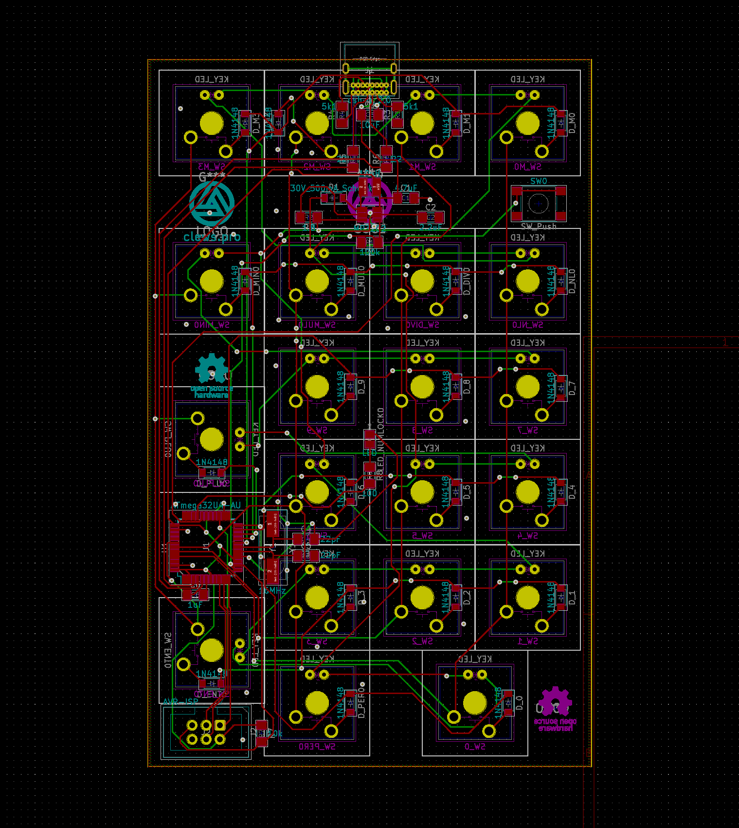
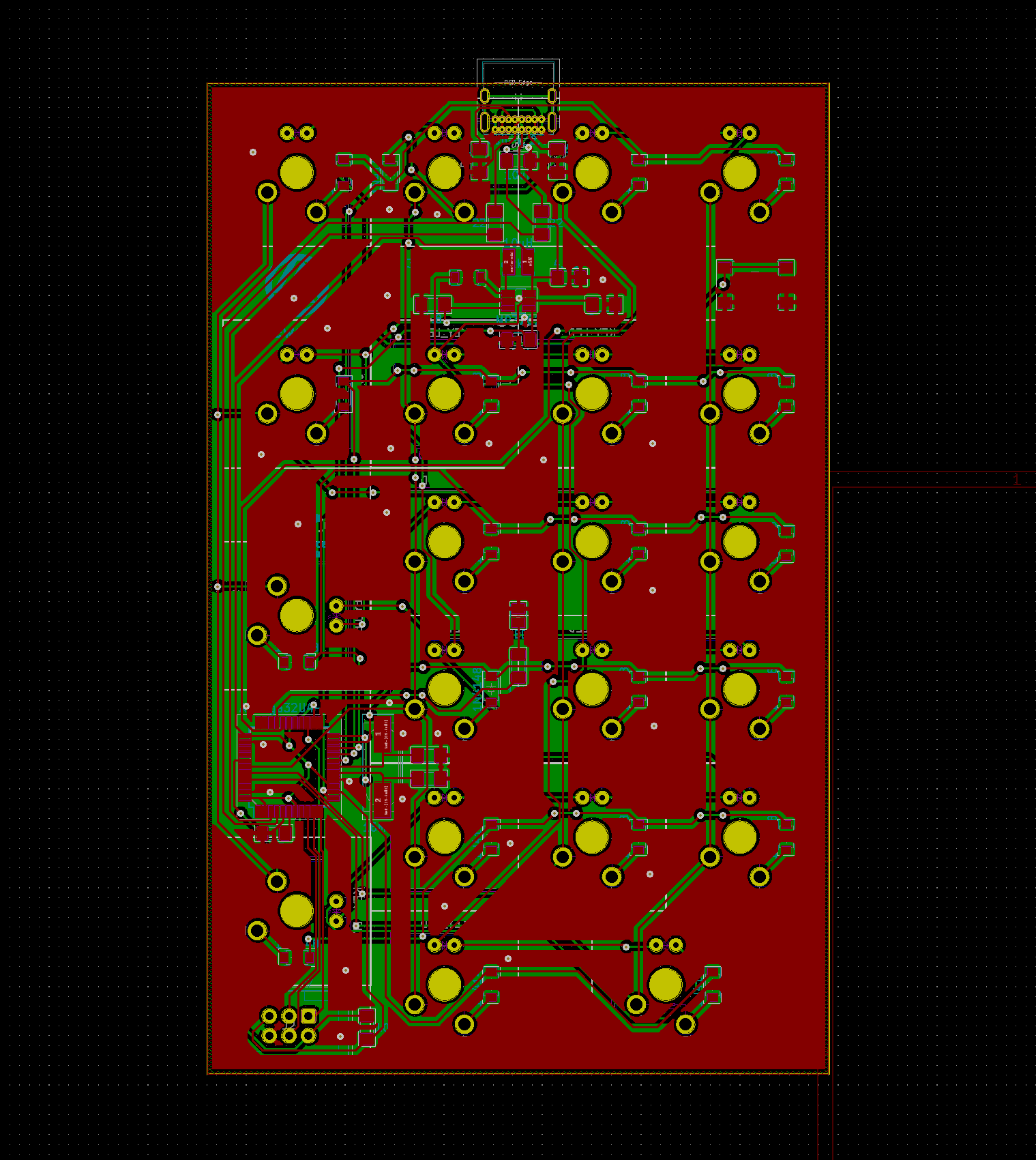
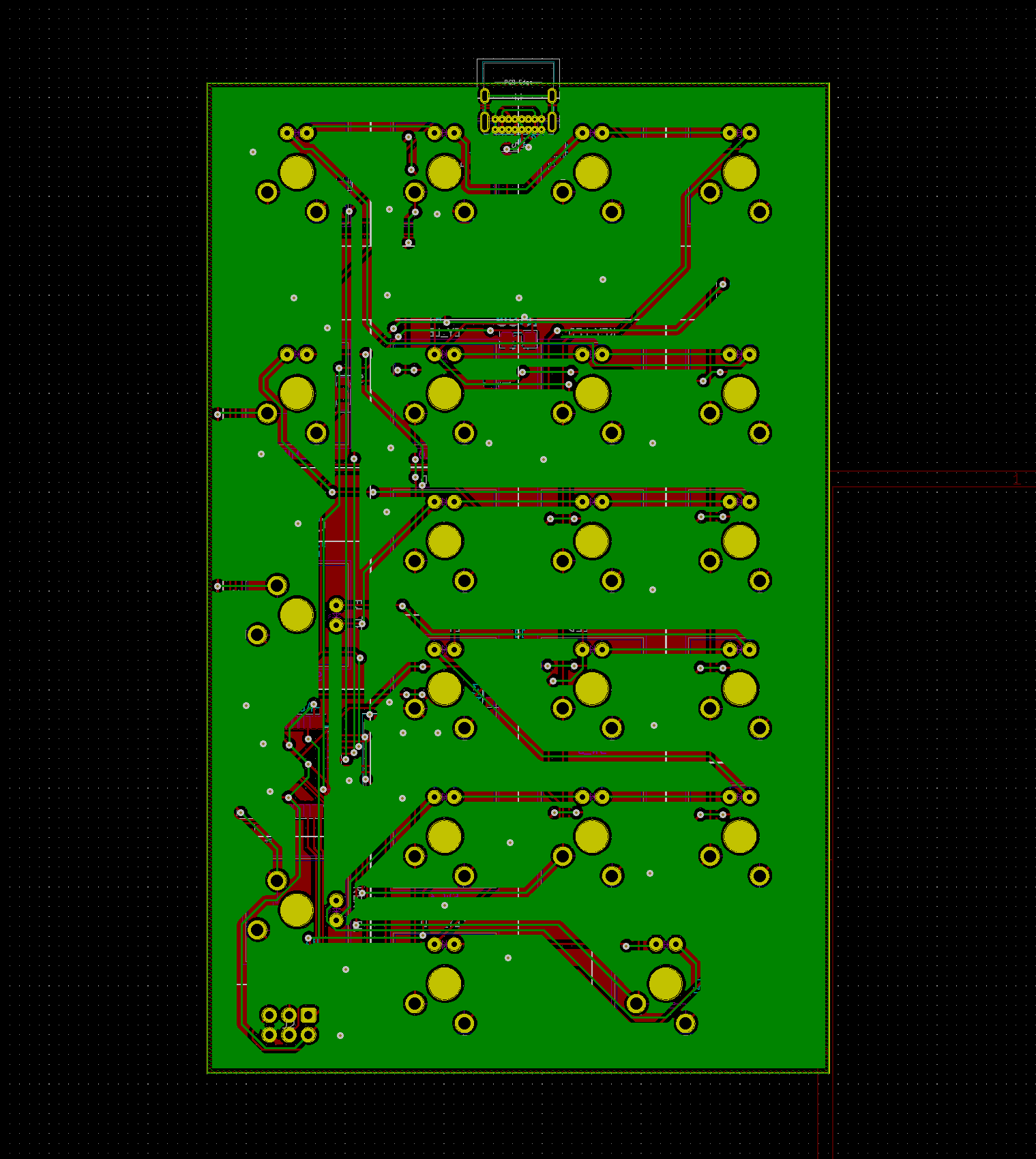
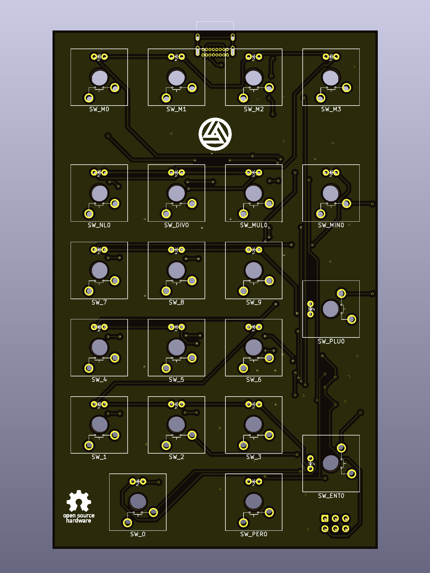
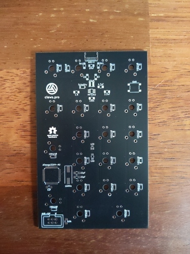
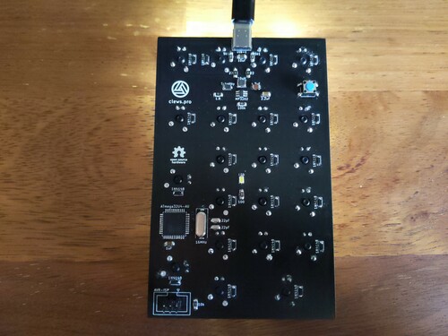
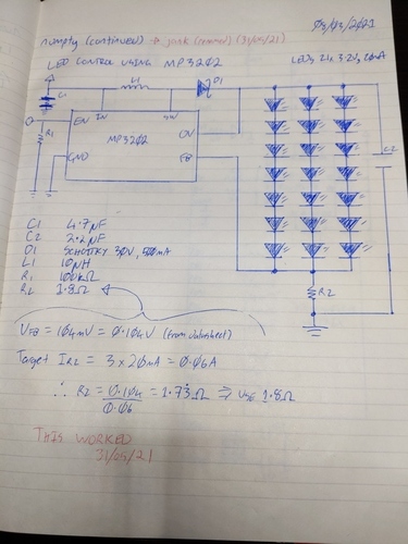
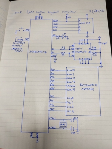
The schematic and PCB layout were designed in KiCAD. The schematic can be divided into five main areas/components:
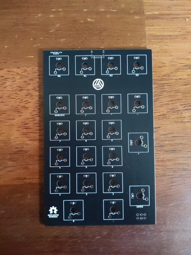
I ordered board fabrication from JLCPCB and had boards in-hand within a week. Sooner than some of the SMD parts which were ordered from a domestic supplier.
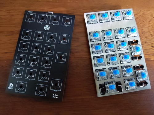
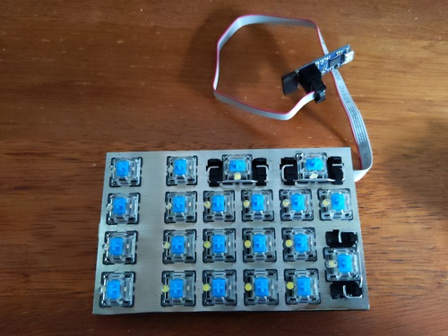
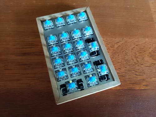
The keyswitches are the "plate-mount" type. Some years ago I ordered some 108-key keyboard plates laser cut from stainless steel. For my first test assembly I took an angle grinder to one of these and cut off just the end keypad section to use with jank. The assembled unit worked well and I eventually made a simple wood enclosure for it which hid the rough-cut edge. I assembled a second unit (minimum order quantity meant I ended up with five PCBs) but this time I ordered a laser-cut stainless steel plate for a nicer finish. To generate the CAD file for the plate, I took the following steps:
Following is the raw data for the layout I created. The actual text on the keys isn't important for creating the plate CAD, but I included it anyway.
["M1","M2","M3","M4"],
[{y:0.5},"Num Lock","/","*","-"],
["7\nHome","8\n↑","9\nPgUp",{h:2},"+"],
["4\n←","5","6\n→"],
["1\nEnd","2\n↓","3\nPgDn",{h:2},"Enter"],
[{w:2},"0\nIns",".\nDel"]
If you want to skip steps 01-07 above (generating the *.dxf CAD file), I have uploaded the file I generated to the GitLab repo (jank_plate_cad.dxf).
Two issues during assembly of the PCB:
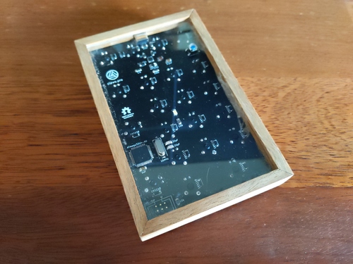
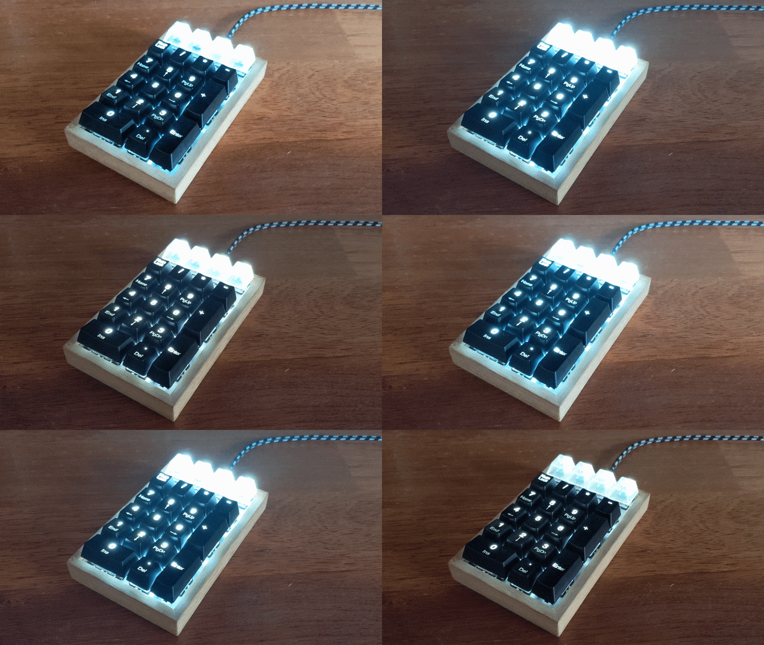
The "enclosure" is a simple wood (spotted gum) frame and a clear acrylic base plate. There is a small hole in the base to provide access to the tact switch that cycles the LED backlighting through various brightness levels and pulse effects.
For the most part, the firmware did not take long as it is heavily based on a previous project - macr0. However I did re-work the macro functionality so that macros could incorporate regular keystrokes and pauses in addition to simple character strings.
The firmware can be separated into four parts:
| ROW0 COL0 | ROW0 COL1 | ROW0 COL2 | ROW0 COL3 |
| ROW1 COL0 | ROW1 COL1 | ROW1 COL2 | ROW1 COL3 |
| ROW2 COL0 | ROW2 COL1 | ROW2 COL2 | ROW2 COL3 |
| ROW3 COL0 | ROW3 COL1 | ROW3 COL2 |
|
| ROW4 COL0 | ROW4 COL1 | ROW4 COL2 | ROW4 COL3 |
ROW5 COL0 | ROW5 COL2 |
||
Porting the firmware from macr0 went relatively smoothly except for one issue that took longer to solve than I will admit. GPIO pins PF4 and PF5 are configured as inputs for reading in key matrix columns 2 and 3. Alternate functions for PF4 and PF5 include JTAG TCK (test clock) and JTAG TMS (test mode select) respectively. I did not intend to use JTAG so this was irrelevant! Of course I now know that JTAG is enabled by default (as it can serve as an interface for programming the AVR) and GPIO is therefore disabled on PF4 and PF5. Disabling JTAG by clearing the applicable fuse bit solved all my problems.
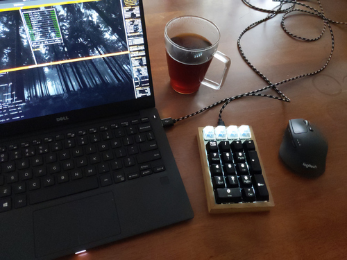
Any key can be configured as a regular keystroke (including media control keys) or a macro (a series of sequential/combined keystrokes). The code as listed on GitLab will cause the top row of keyswitches to be configured as four macro keys while the remaining 17 keys are configured as a traditional numeric keypad, including standard Num Lock operation.
Only the keymap.c source file needs to be modified in order to configure the action for each key. The keymap.h header file is a useful reference, particularly for finding all the defined keyboard scan-codes.
So a keystroke configured as a macro actually triggers a series of one or more single "macro actions". The series of macro actions are defined within a multi-dimensional array MACROMAP[number_of_rows][number_of_columns][number_of_macro_t]. A single macro action is represented as a custom structure type named macro_t. The type definition (typedef) for the structure is listed within the keymap.h header file, and is also duplicated below for reference:
typedef struct {
uint8_t m_action; // m_action defines the kind of macro action (string, keys or delay).
char m_array[MAX_MACRO_CHARS]; // m_array is interpreted differently depending on the value of m_action.
} macro_t;
The array part of the macro_t structure (m_array) is interpreted in different ways by the SendMacroReports() function, depending on the value of the interger part of the structure (m_action).
| m_action | m_array |
|---|---|
| M_NULL | No macro. The m_array is ignored. |
| M_STRING | "Type" a string of characters. The m_array is interpreted as a character array. Each character is converted to the required keyboard scancode and sequentially sent as a series of keyboard reports. |
| M_KEYS | A combination of keystrokes (including modifiers). Each element of m_array is interpreted as a keyboard scancode. All scancodes are sent simultaneously in a single keyboard report. |
| M_WAIT | No keystrokes. Each element of the m_array is interpreted as an integer. The value of each integer represents the number of seconds to "wait". Such a delay can be useful if previous macro keystrokes need time for the corresponding command to execute. |
#include "keymap.h"
// Define the physical row and column pins on the microcontroller to be scanned for key presses.
const uint8_t key_row_array[] = {ROW1, ROW2, ROW3, ROW4, ROW5};
const uint8_t key_col_array[] = {COL0, COL1, COL2, COL3};
const uint8_t macro_row_array[] = {ROW0};
const uint8_t macro_col_array[] = {COL0, COL1, COL2, COL3};
// Number pad key definitions.
// KEY_X_Y where X:Row Number, Y:Column Number.
#define KEY_1_0 HID_KEYBOARD_SC_NUM_LOCK
#define KEY_1_1 HID_KEYBOARD_SC_KEYPAD_SLASH
#define KEY_1_2 HID_KEYBOARD_SC_KEYPAD_ASTERISK
#define KEY_1_3 HID_KEYBOARD_SC_KEYPAD_MINUS
#define KEY_2_0 HID_KEYBOARD_SC_KEYPAD_7_AND_HOME
#define KEY_2_1 HID_KEYBOARD_SC_KEYPAD_8_AND_UP_ARROW
#define KEY_2_2 HID_KEYBOARD_SC_KEYPAD_9_AND_PAGE_UP
#define KEY_2_3 HID_KEYBOARD_SC_KEYPAD_PLUS
#define KEY_3_0 HID_KEYBOARD_SC_KEYPAD_4_AND_LEFT_ARROW
#define KEY_3_1 HID_KEYBOARD_SC_KEYPAD_5
#define KEY_3_2 HID_KEYBOARD_SC_KEYPAD_6_AND_RIGHT_ARROW
#define KEY_3_3 0x00 // No key here.
#define KEY_4_0 HID_KEYBOARD_SC_KEYPAD_1_AND_END
#define KEY_4_1 HID_KEYBOARD_SC_KEYPAD_2_AND_DOWN_ARROW
#define KEY_4_2 HID_KEYBOARD_SC_KEYPAD_3_AND_PAGE_DOWN
#define KEY_4_3 HID_KEYBOARD_SC_KEYPAD_ENTER
#define KEY_5_0 HID_KEYBOARD_SC_KEYPAD_0_AND_INSERT
#define KEY_5_1 0x00 // No key here.
#define KEY_5_2 HID_KEYBOARD_SC_KEYPAD_DOT_AND_DELETE
#define KEY_5_3 0x00 // No key here.
// The key map array - for regular key strokes including media control keys.
const char KEYMAP[NUM_KEY_ROWS][NUM_KEY_COLS] PROGMEM = {
//Col 0 Col 1 Col 2 Col 3
{KEY_1_0, KEY_1_1, KEY_1_2, KEY_1_3}, // Row 1
{KEY_2_0, KEY_2_1, KEY_2_2, KEY_2_3}, // Row 2
{KEY_3_0, KEY_3_1, KEY_3_2, KEY_3_3}, // Row 3
{KEY_4_0, KEY_4_1, KEY_4_2, KEY_4_3}, // Row 4
{KEY_5_0, KEY_5_1, KEY_5_2, KEY_5_3} // Row 5
};
// The macro map array - for key strokes that are mapped as macros.
const macro_t MACROMAP[NUM_MACRO_ROWS][NUM_MACRO_COLS][MAX_MACRO_ACTIONS] PROGMEM =
{
{ //Row0
{ //Col0
{M_KEYS, {HID_KEYBOARD_SC_F12}}, // This macro is just the same as hitting the F12 key.
},
{ //Col1
{M_KEYS, {HID_KEYBOARD_SC_LEFT_GUI}}, // This macro will go to the specified url in a new firefox tab.
{M_WAIT, {1}},
{M_STRING, "firefox"},
{M_KEYS, {HID_KEYBOARD_SC_ENTER}},
{M_WAIT, {3}},
{M_KEYS, {HID_KEYBOARD_SC_LEFT_CONTROL, HID_KEYBOARD_SC_T}},
{M_STRING, "https://clews.pro/projects/jank.php"},
{M_KEYS, {HID_KEYBOARD_SC_ENTER}},
},
{ //Col2
{M_STRING, " _\n"}, // This macro will enter a series of strings to create some ascii art.
{M_STRING, " ( )\n"},
{M_STRING, " H\n"},
{M_STRING, " H\n"},
{M_STRING, " _H_\n"},
{M_STRING, " .-'-.-'-.\n"},
{M_STRING, " / \\\n"},
{M_STRING, "| |\n"},
{M_STRING, "| .-------'._\n"},
{M_STRING, "| / / '.' '. \\\n"},
{M_STRING, "| \\ \\ @ @ / /\n"},
{M_STRING, "| '---------'\n"},
{M_STRING, "| _______|\n"},
{M_STRING, "| .'-+-+-+|\n"},
{M_STRING, "| '.-+-+-+|\n"},
{M_STRING, "| '''''' |\n"},
{M_STRING, "'-.__ __.-'\n"},
{M_STRING, " '''\n"}
},
{ //Col3
{M_STRING, "Bender is Great!"}, // This macro will type a string of characters then hit enter.
{M_KEYS, {HID_KEYBOARD_SC_ENTER}},
}
}
};
Using the configuration above, the macro mapped to the key at row 0, column 1 is an example that uses all three types of macro actions (string, keys and wait).
If no macros are wanted, the top four keys can be included in the KEYMAP array while leaving the MACROMAP array empty. In the following example, the numeric keypad remains the same as the example above, but the top four keys (row 0) are configured as media controls.
#include "keymap.h"
// Define the physical row and column pins on the microcontroller to be scanned for key presses.
const uint8_t key_row_array[] = {ROW0, ROW1, ROW2, ROW3, ROW4, ROW5};
const uint8_t key_col_array[] = {COL0, COL1, COL2, COL3};
const uint8_t macro_row_array[] = {};
const uint8_t macro_col_array[] = {};
// Number pad key definitions.
// KEY_X_Y where X:Row Number, Y:Column Number.
#define KEY_0_0 HID_MEDIACONTROLLER_SC_TOGGLE
#define KEY_0_1 HID_MEDIACONTROLLER_SC_STOP
#define KEY_0_2 HID_MEDIACONTROLLER_SC_PREVIOUS
#define KEY_0_3 HID_MEDIACONTROLLER_SC_NEXT
#define KEY_1_0 HID_KEYBOARD_SC_NUM_LOCK
#define KEY_1_1 HID_KEYBOARD_SC_KEYPAD_SLASH
#define KEY_1_2 HID_KEYBOARD_SC_KEYPAD_ASTERISK
#define KEY_1_3 HID_KEYBOARD_SC_KEYPAD_MINUS
#define KEY_2_0 HID_KEYBOARD_SC_KEYPAD_7_AND_HOME
#define KEY_2_1 HID_KEYBOARD_SC_KEYPAD_8_AND_UP_ARROW
#define KEY_2_2 HID_KEYBOARD_SC_KEYPAD_9_AND_PAGE_UP
#define KEY_2_3 HID_KEYBOARD_SC_KEYPAD_PLUS
#define KEY_3_0 HID_KEYBOARD_SC_KEYPAD_4_AND_LEFT_ARROW
#define KEY_3_1 HID_KEYBOARD_SC_KEYPAD_5
#define KEY_3_2 HID_KEYBOARD_SC_KEYPAD_6_AND_RIGHT_ARROW
#define KEY_3_3 0x00 // No key here.
#define KEY_4_0 HID_KEYBOARD_SC_KEYPAD_1_AND_END
#define KEY_4_1 HID_KEYBOARD_SC_KEYPAD_2_AND_DOWN_ARROW
#define KEY_4_2 HID_KEYBOARD_SC_KEYPAD_3_AND_PAGE_DOWN
#define KEY_4_3 HID_KEYBOARD_SC_KEYPAD_ENTER
#define KEY_5_0 HID_KEYBOARD_SC_KEYPAD_0_AND_INSERT
#define KEY_5_1 0x00 // No key here.
#define KEY_5_2 HID_KEYBOARD_SC_KEYPAD_DOT_AND_DELETE
#define KEY_5_3 0x00 // No key here.
// The key map array - for regular key strokes including media control keys.
const char KEYMAP[NUM_KEY_ROWS][NUM_KEY_COLS] PROGMEM = {
//Col 0 Col 1 Col 2 Col 3
{KEY_0_0, KEY_0_1, KEY_0_2, KEY_0_3}, // Row 1
{KEY_1_0, KEY_1_1, KEY_1_2, KEY_1_3}, // Row 1
{KEY_2_0, KEY_2_1, KEY_2_2, KEY_2_3}, // Row 2
{KEY_3_0, KEY_3_1, KEY_3_2, KEY_3_3}, // Row 3
{KEY_4_0, KEY_4_1, KEY_4_2, KEY_4_3}, // Row 4
{KEY_5_0, KEY_5_1, KEY_5_2, KEY_5_3} // Row 5
};
// The macro map array - for key strokes that are mapped as macros.
const macro_t MACROMAP[NUM_MACRO_ROWS][NUM_MACRO_COLS][MAX_MACRO_ACTIONS] PROGMEM = {};
If I ever do a revision, I'll make an adjustment to the LED controller circuit. I implemented the PWM brightness control using the basic configuration as per figure 7 of the MP3202 datasheet. This arrangement is for dimming with a PWM frequency of no higher than 1kHz. This seemed fine for my purpose, however what I didn't think of was the hum from the inductor. It's only audible if the room is otherwise silent, but I could have eliminated it completely with a PWM frequency above the human-audible range. I should have configured the circuit in accordance with figure 8 of the datasheet which can tolerate higher frequencies because it has some additional passives for filtering the PWM signal.
 |
 |
 |
 |
 |
 |
 |
 |
 |
 |
 |
 |
 |
 |
 |
 |
 |
 |
 |
 |
 |
 |
 |
 |