clewsy
A work-in-progress
Off-the-shelf wifi-connected mains switches are pretty common now, but from what I understand, they typically require some kind of cloud service subscription or account (at least at the time I developed this project).
I am loath to sign up for such an account and even more so, I want to retain control within my local network, with external control only via specific protocols & ports under my control.
By combining a cheap (<$.0AUD) remote mains adapter kit with an RF remote control and a Raspberry Pi Zero W, I developed a custom solution.
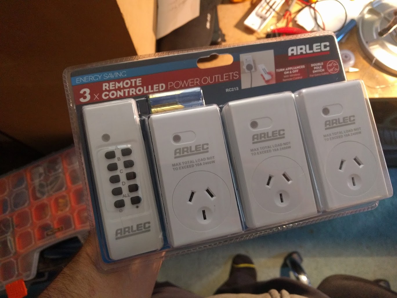
I started off with a mains outlet remote control kit I found at Bunnings. It's an Arlec branded kit and works by transmitting on the 433.92MHz band. The remote can control up to four channels (A, B, C & D).
To interface the remote control I had to reverse engineer it. I assumed it would be a matter of tracing the button pads and finding a point to which I could connect a GPIO pin on the Raspberry Pi and simply pull up or down to trigger.
This wasn't the case - I found that the button pads were matrixed, so triggering a channel required connecting two specific points with each other, depending on the channel and the desired action ("on" or "off").
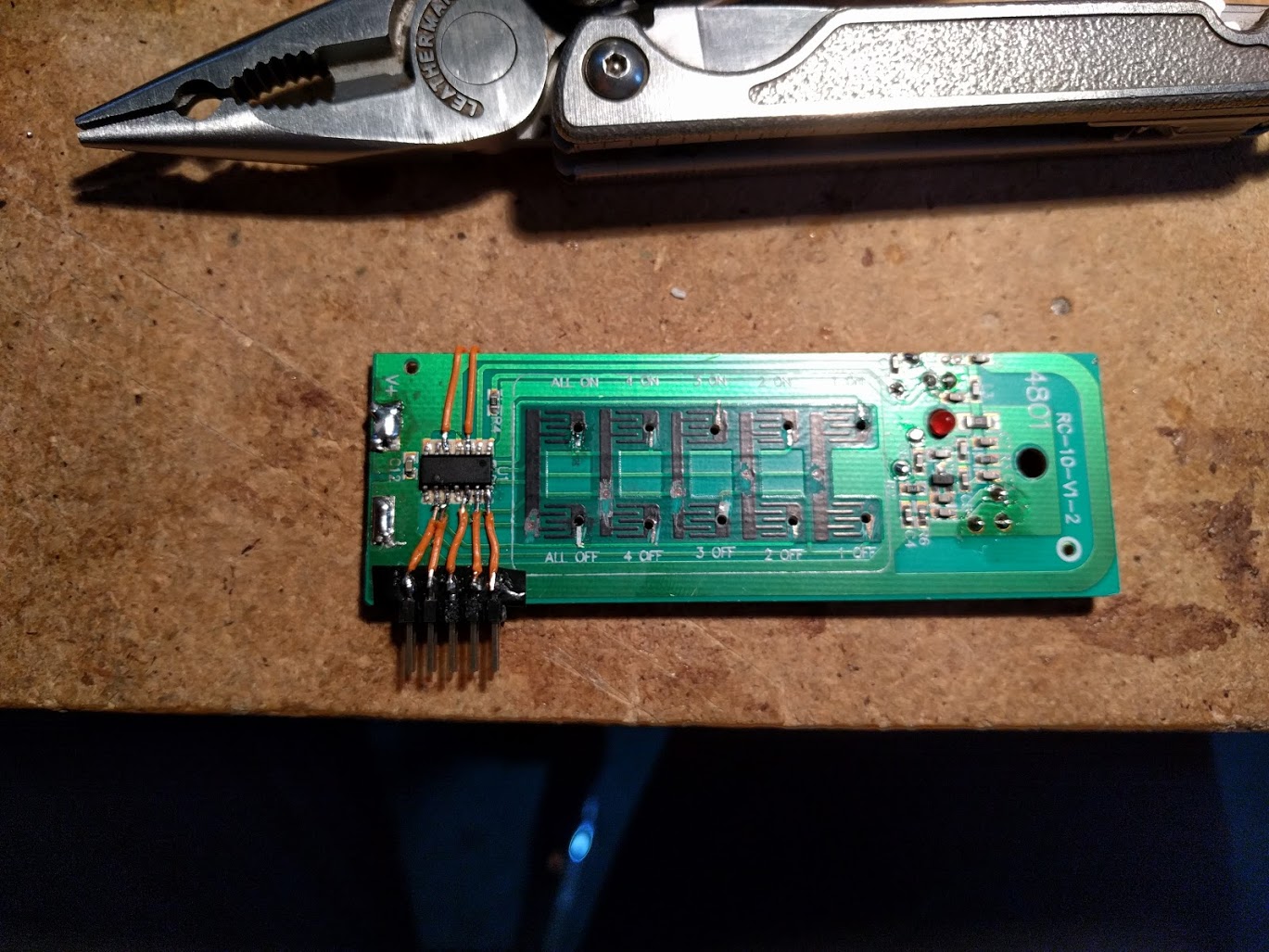
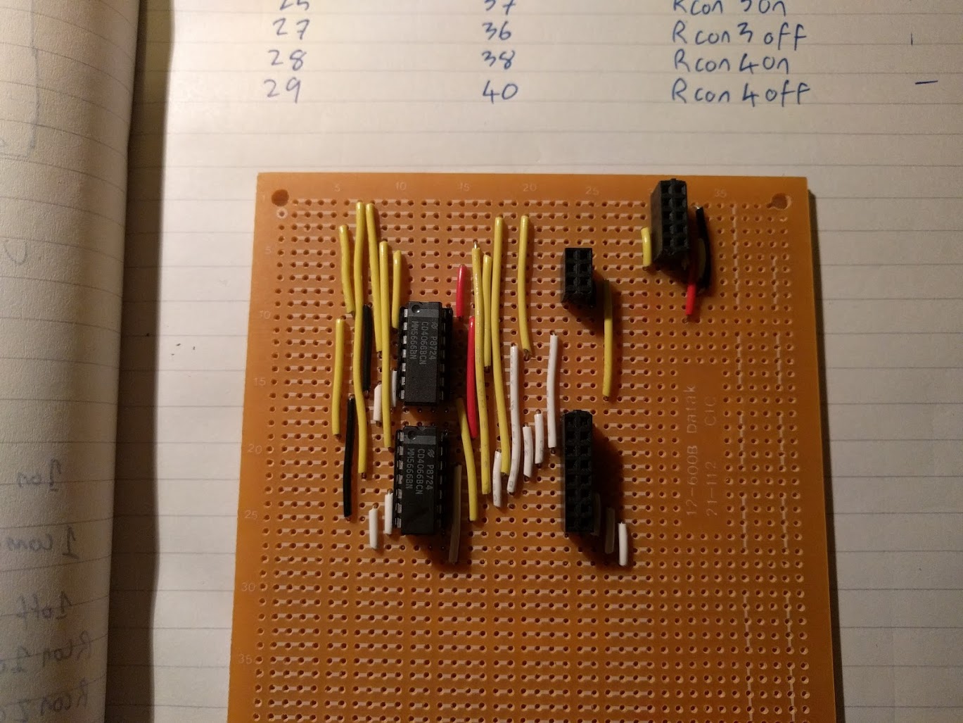
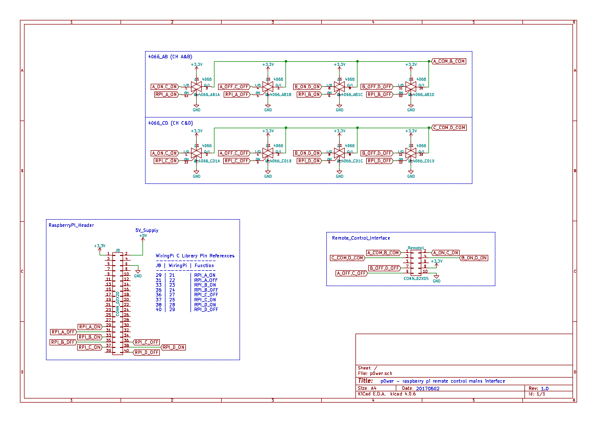
As such, instead of direcly connecting the remote to the GPIO, I used the GPIO to trigger bilateral switches within a couple of 4066 CMOS quad bilateral switch packages. These switches then short the two contacts to emulate a button press on the remote.
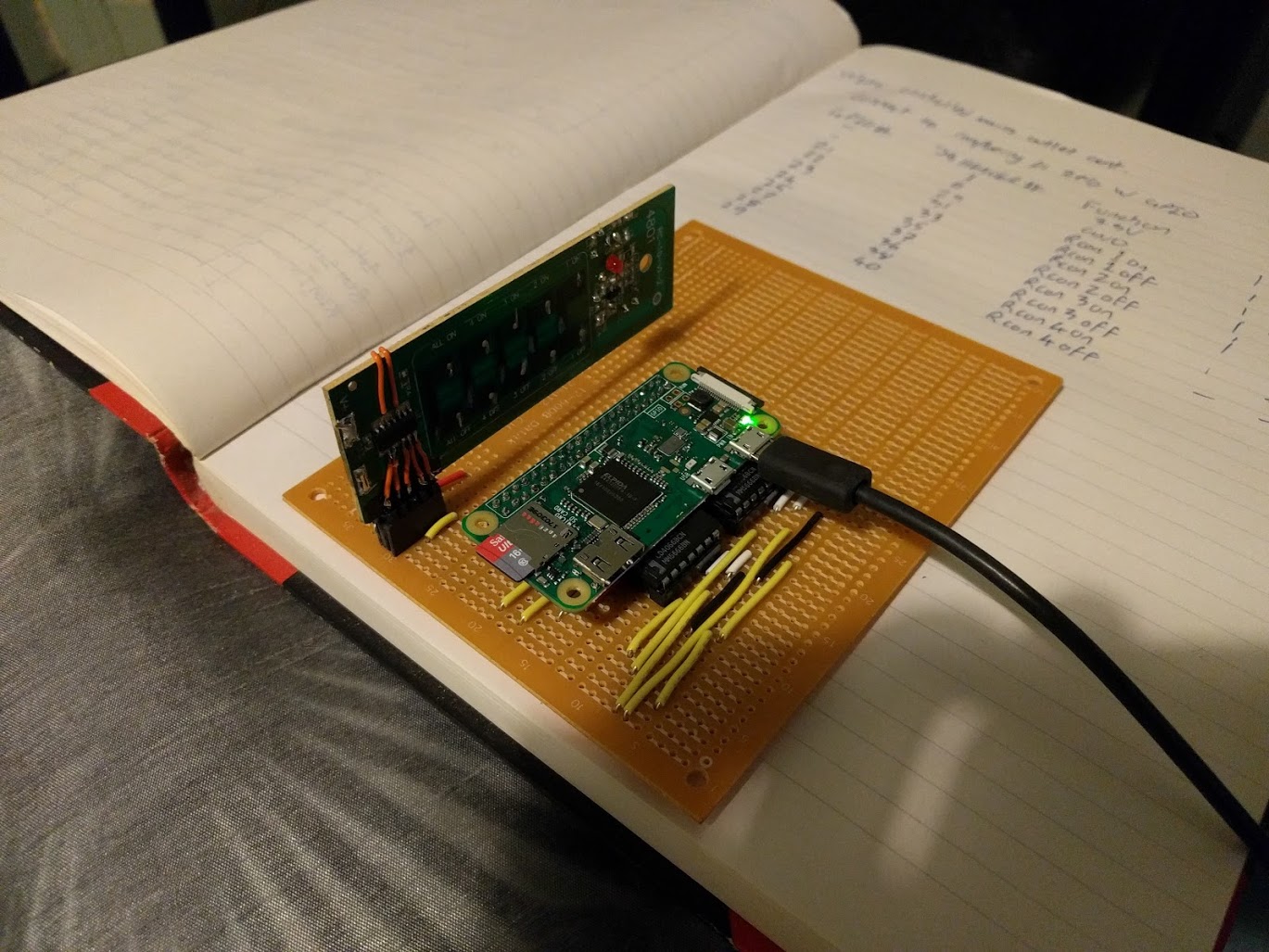
I broke out the contacts on the remote via a pin-header and assembled the intermediate interface circuit on some proto-board.
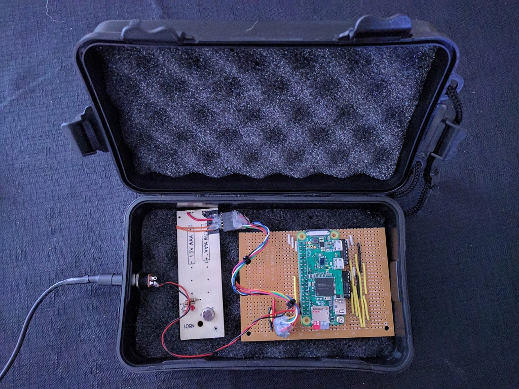
The final assembled interface circuit included headers for connecting the raspbrry pi and the hacked remote.
I added a barrel jack for power and put the assembly inside a dust-resistant plastic case.
In C I wrote a program that takes the desired channel (A, B, C or D) and desired action ("on" or "off") and then pulses the remote control to emulate pressing the desired button.
The code and KiCad files are on the gitlab repo.
The program interfaces with the gpio via the wiringpi pigpio library.
Program usage follows:
$ sudo p0wer <channel(a,b,c,d)> <on/off>
Super user access is required for manipulation of the gpio pins.
On the raspberry pi install the pigpio library:
$ sudo apt update
$ sudo apt install pigpio
Clone this repository and enter the cloned project directory:
$ git clone https://gitlab.com/clewsy/p0wer
$ cd p0wer
Compile and install the executable:
$ sudo make install
The binary is now ready to use. This can be tested by running the command with no arguments. It should print the usage to screen.
$ p0wer
Usage: p0wer <channel(a,b,c,d)> <on/off>
NOTE using the sudo make install command as per the instructions above will automatically set the SUID bit (i.e. set the setuid flag) for the executable file. This means it is executed with owner (root) privileges. As such, it can be run (and the GPIO pins can be manipulated) with out prepending the command with sudo. If you want to install the file without this permission, use the following commands instead of running sudo make install:
$ make
$ sudo cp p0wer /usr/local/sbin/p0wer
In the future, I intend to facillitate switching of these mains outlet units via a web-server. However until I finish that project, manipulating the outlets is done by running the compiled program.
(Alternatively, I also have a second, non-hacked remote that similarly facillitates control of the outlets.)
I currently use a Termux shortcut on my android smartphone to run a script that calls the program on the pi. By pressing a button on my homescreen, I can, for example, switch on a lamp in the lounge room.
The script will connect to the raspberry pi (using ssh) and run the program with the desired inputs.
The following example two-line script will connect to the pi and run the program with the options to turn on the channel A outlet:
#!/bin/bash
ssh home.server 'ssh raspberry.pi "sudo p0wer a on"'
The full termux script I wrote is a bit more robust (and documented on gitlab).
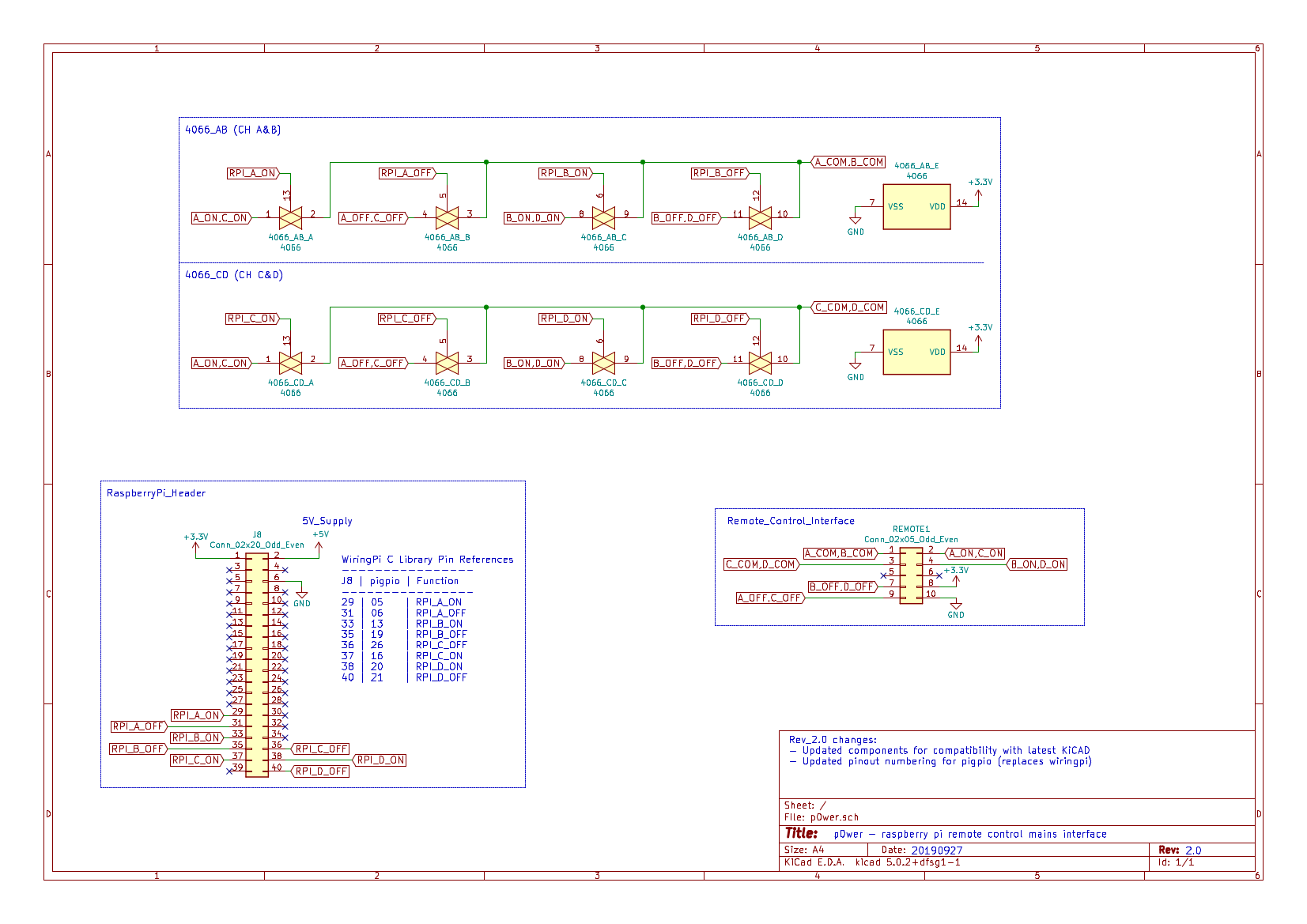
In August 2019, support ceased for the wiringPi library. As such, I revised the code to instead utilise the pigpio library.
While I was at it, I updated the KiCad schematic to work with the latest KiCad revision.
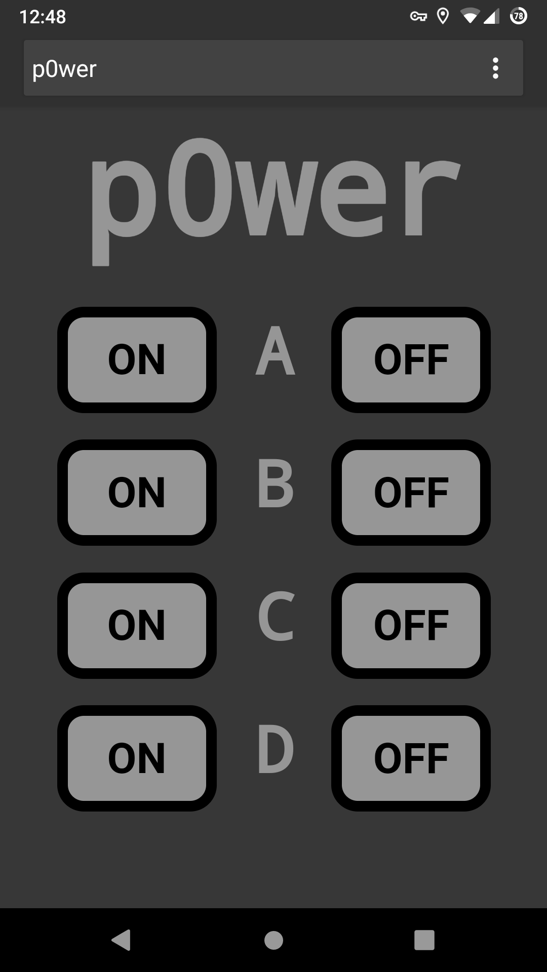
In December 2019, I decided to create a web interface for controlling all 4 channels from a browser. I wrote a simple php script and combined it with some basic html and css. Combined with Apache and php installed on the raspberry pi, I am now able to control power points from any browser with access to the local network. To achieve this I learned about setting the SUID bit on an executable so that when called by the web user (www-data) it is still executed as root. WebUI setup instructions can be found in the README at gitlab.
As a bonus, the webui allows me to script control of the remote mains units using a curl command as an alternative to ssh. Using curl to control the outlets enables simple integration into automation platforms such as openHAB or Home Assistant. The following example commands produce an equivalent result (turning on channel a).
Using ssh (user pi on host raspberrypi):
$ ssh pi@raspberrypi "sudo p0wer a on"
Using curl (hostname raspberrypi or host IP 192.168.1.123):
$ curl --silent http://raspberrypi/index.php?a=ON >> /dev/null
or
$ curl --silent http://192.168.1.123/index.php?a=ON >> /dev/null
As part of another project (clewsy_ansible) I have automated installation of the p0wer executable and the webui. Starting with a fresh Raspberry Pi OS installation on a raspberry pi zero, I can run a single playbook that will:
See the clewsy_ansible gitlab repository and specifically the p0wer role for more information.
 |
 |
 |
 |
 |
 |