clewsy
A work-in-progress

This project combined a handful of smaller project ideas:
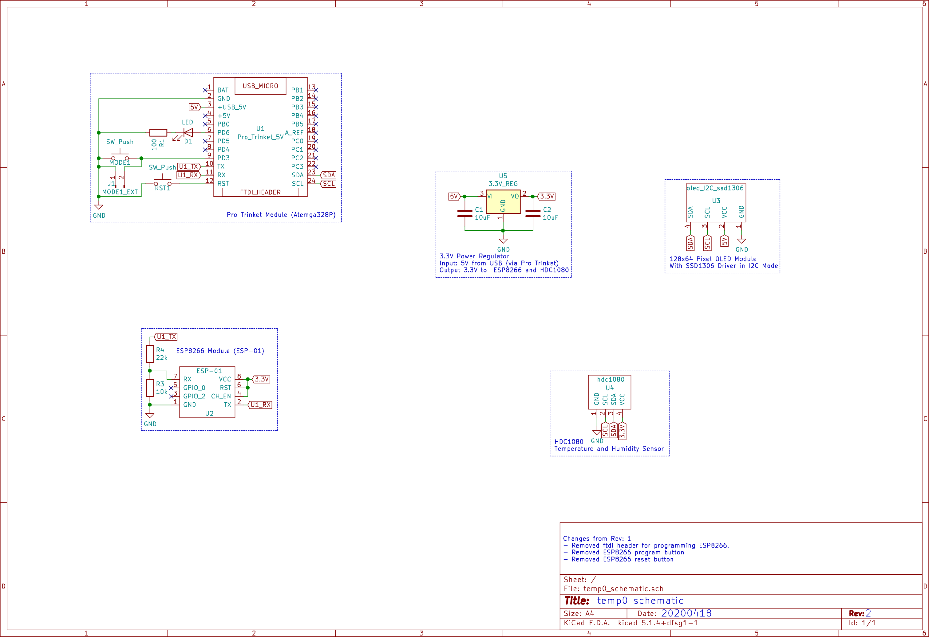
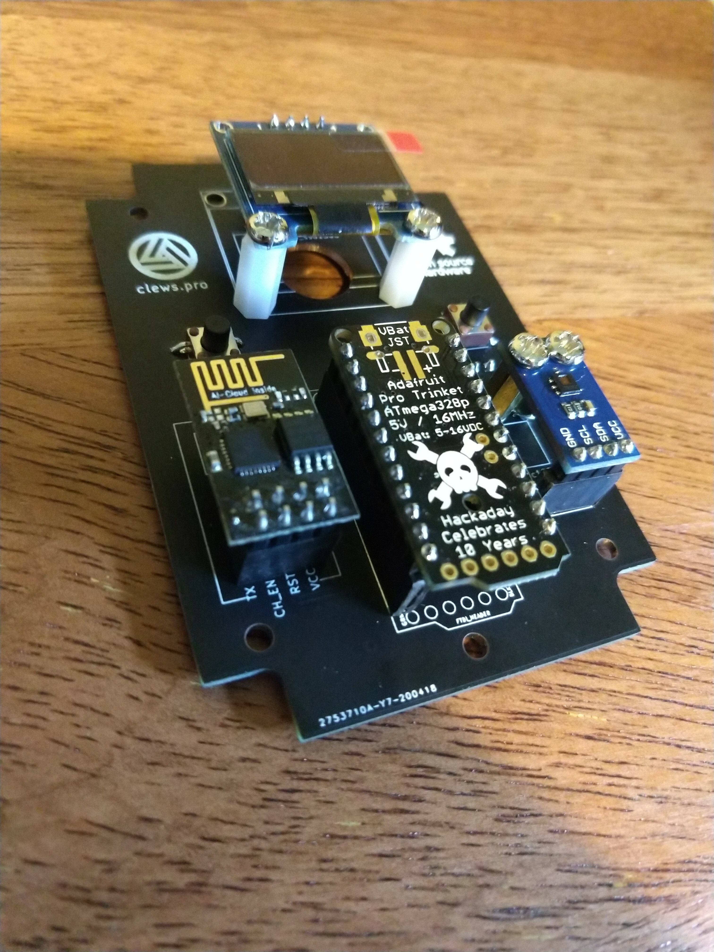
The final system is comprised of the following main components:
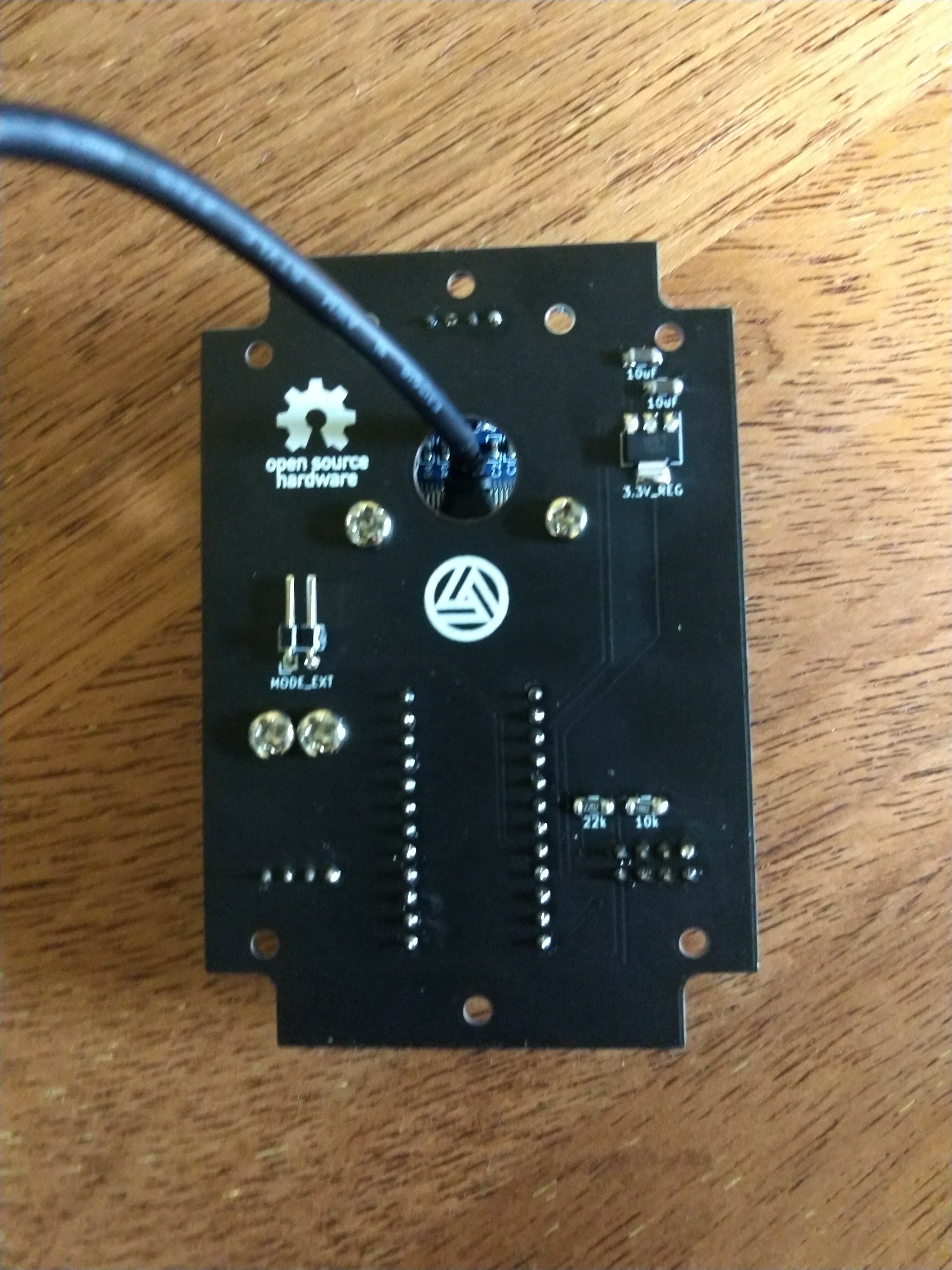
There are a few additional minor components for level-shifting serial comms and regulating 5V from USB down to 3.3V for the ESP8266 and HDC1080.
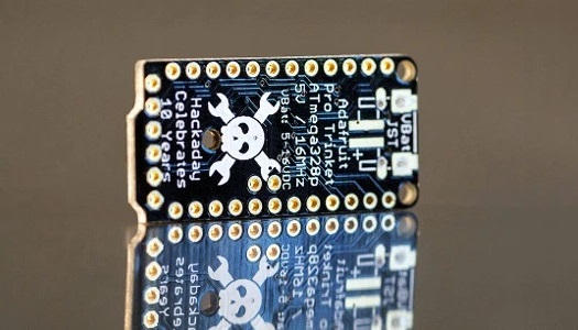
It would be possible to create a similar device without a Pro Trinket, utilising more of the ESP8266 capability, but I wanted an excuse to use one of these Hackaday special edition modules.
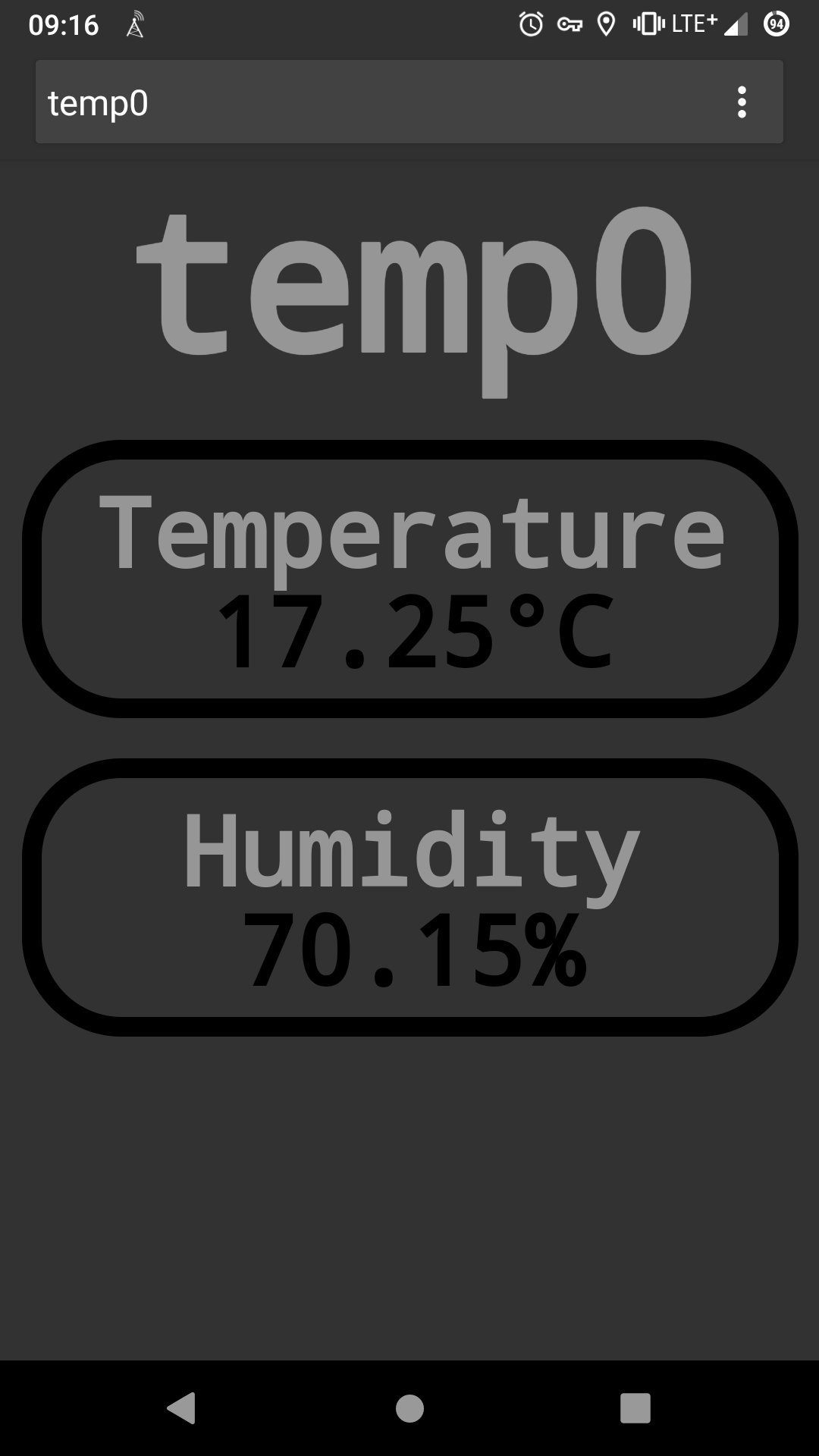
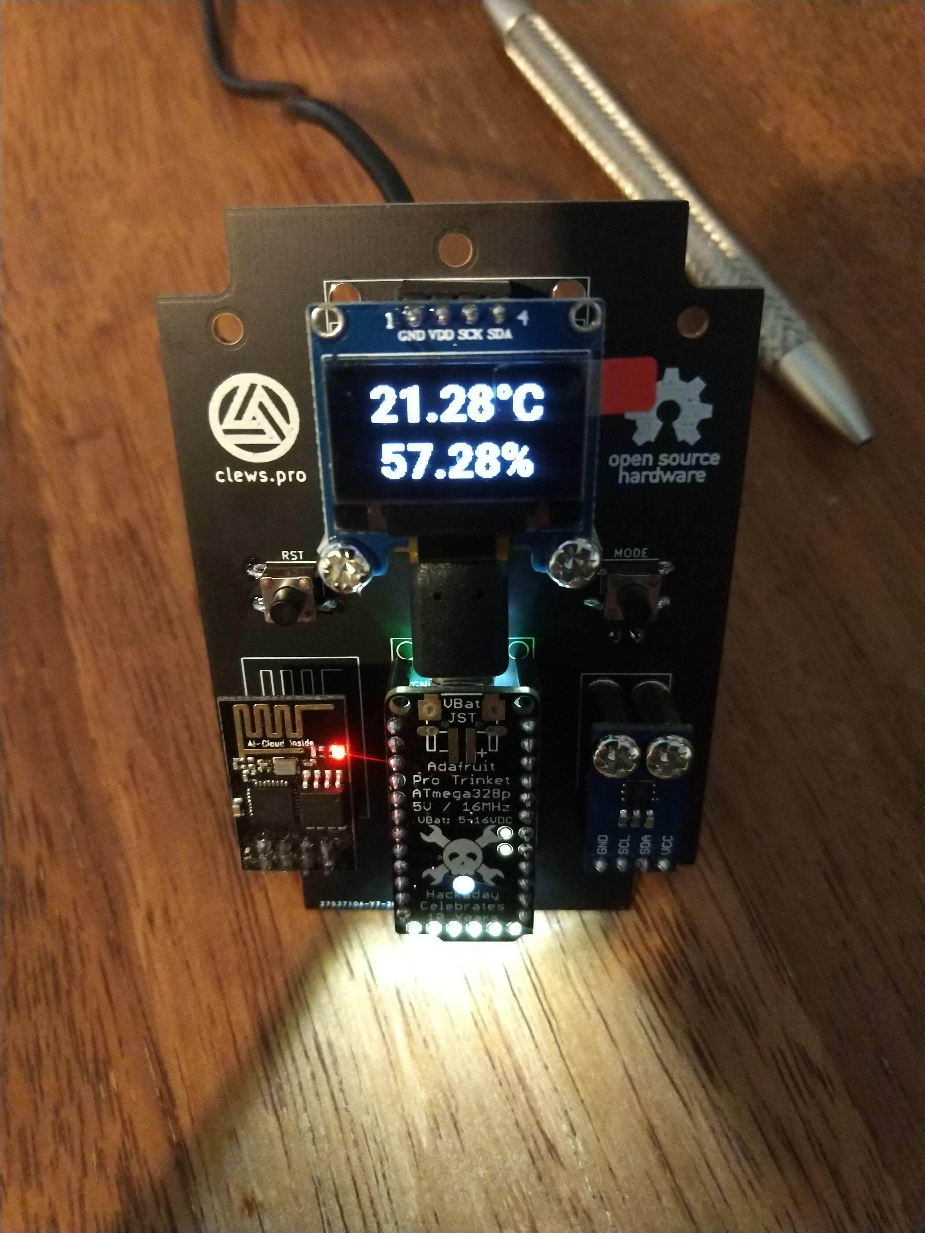
The ESP8266 serves a pretty HTML page at the index (http://temp0/) which shows the current temperature and humidity readings.
Certain sub-directories of the web-server will provide plain-text values of the temperature or humidity. This is useful for home-automation implementatins (e.g. Home Assistant).
The ESP8266 hostname is set to "temp0", making the useful http addresses as follows:
From a command line, a simple use of "curl" will provide plain-text temperature and humidity values for simple integration into other systems.
$ curl http://temp0/temperature
15.68
$ curl http://temp0/humidity
70.69
Code (for the Pro-Trinket and the ESP8266) and KiCAD schematic/layout can all be found at the GitLab repo.
Meh, the Arduino IDE wasn't much fun and I thought it felt a little dated, so I started looking into alternatives. I first tried the VSCode Arduino extension which took some configuring but eventually worked. Though I moved on from that when I discovered a better solution - the PlatformIO IDE extension for VSCode. This was easy to set up and start using. It adds a few buttons to the VSCode interface for compiling and uploading to a connected device. Being a VSCode extension means I also have an integrated terminal console and integrated git management. After a few weeks back-and-forth with PlatformIO I came to really like it and plan to use it for future embedded projects, even if I don't continue with the arduino bootloader.
The standard arduino libraries are handy though. In this project I used Serial (comms between Trinket and ESP8266) and Wire (I2C comms for Trinket/SD1306 and Trinket/HDC1080). These libraries made it super-fast to get going with the low-level comms.
For both the SSD1306 OLED and HDC1080 Sensor however, I opted to write my own drivers rather than use existing libraries. Partly because it keeps the drivers more minimal and project-specific, and also partly because it was a fun learning experience to create C++ classes.
While programming the ESP8266 I drew from existing example libraries. At first I implemented some basic web-server functionality using AT commands sent from the Trinket over serial to the default ESP8266 firmware, but ultimately I switched to the more robust ESP8266 Arduino Core libraries. I was super impressed with the capability of the ESP-01 module combined with these libraries.
I had some prior familiarity with the SSD1306 OLED driver on a previous project. There are a few differences this time in the way I implemented the driver:
To display text on the oled, I can now just specify a font array plus coordinates, and the char/string functions will output to the SSD1306/OLED regardless of character widths and font height. To create the char/string functions I started with a font file generator created by Daniel Eichhorn to generate a couple of fonts with dimensions I thought would suit the project. After getting my head around the font and character metadata embedded in the array, I was able to create the print_char and print_string functions. The code has a lot of comments around these functions that I added as I went - this is part of my learning process, plus I'm sure I'll have to re-learn this one day when I return to the project for whatever reason.
The HDC1080 is a temperature and humidity sensor that interfaces over I2C. Similar to the OLED/SSD1306, I wrote a project-specific driver for it.
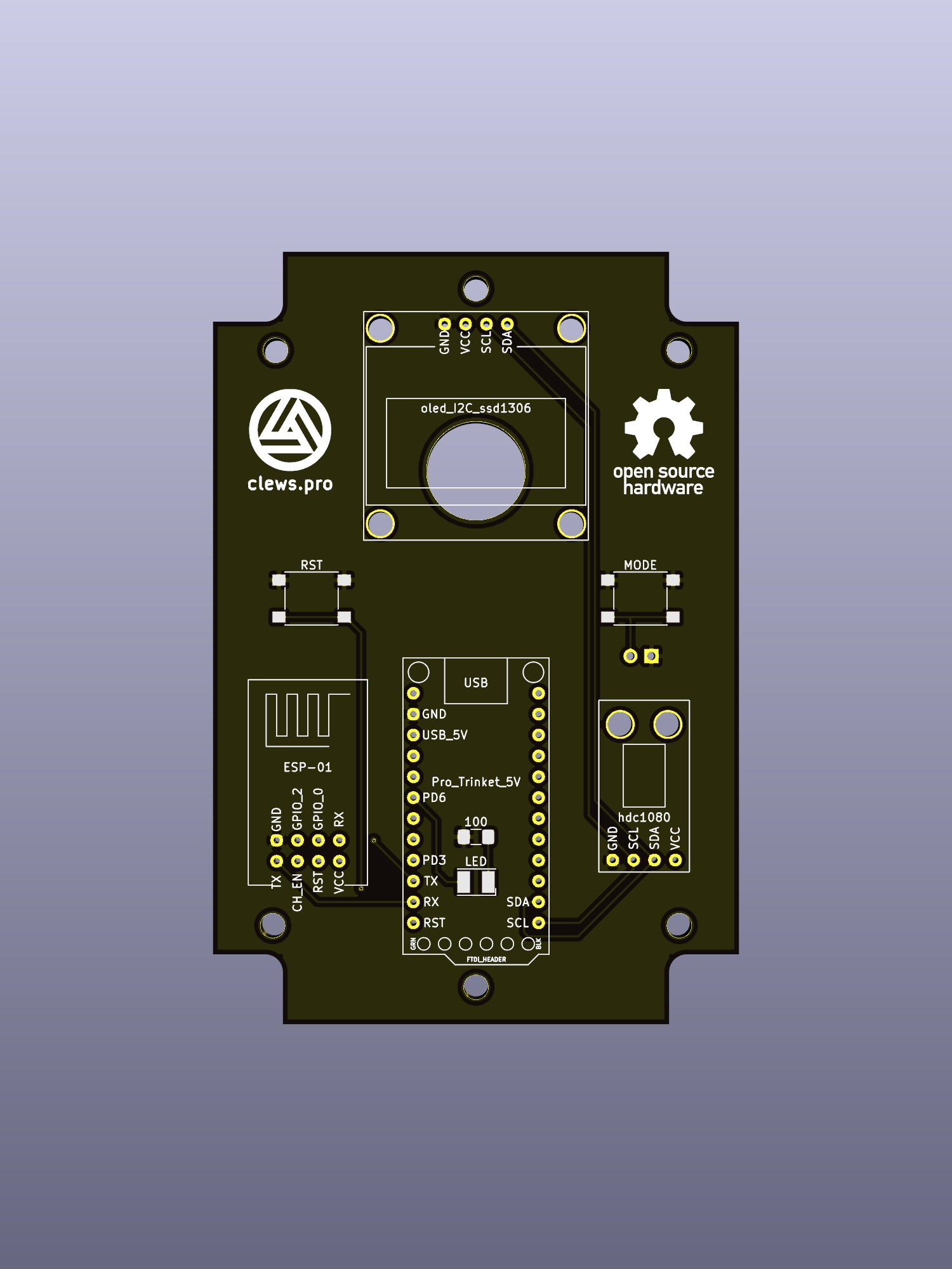
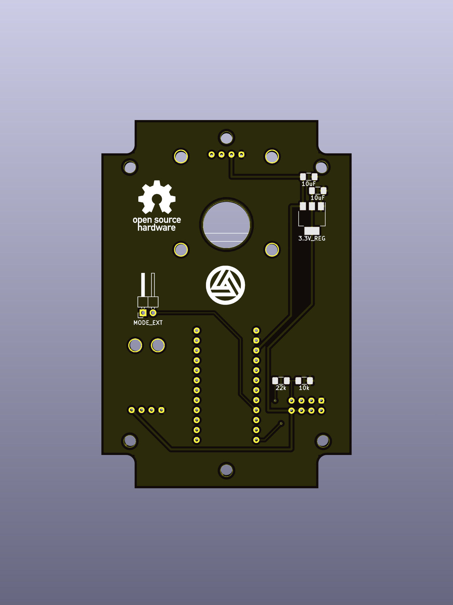
When testing the prototype on a breadboard, I had the sensor attached with jumper leads which gave it ~100mm clearance from the rest of the components. This worked fine and temperature readings matched a thermometer I used for comparison. However my first assembled PCB reported temperatures 3-4 degrees higher. I located the sensor on the PCB too close to the 3.3V regulator, so the waste heat was affecting the temperature readings. For the subsequent iteration of the PCB, these two components were located at opposite corners and sides of the PCB to give the regulator additional copper into which it could dissipate heat. This improved the accuracy of the sensor readings, but it was still showing higher than my callibration thermometer. Fortunately the delta was a consistent value regardless of temperature so ultimately I added a bodge-factor in code to compensate.
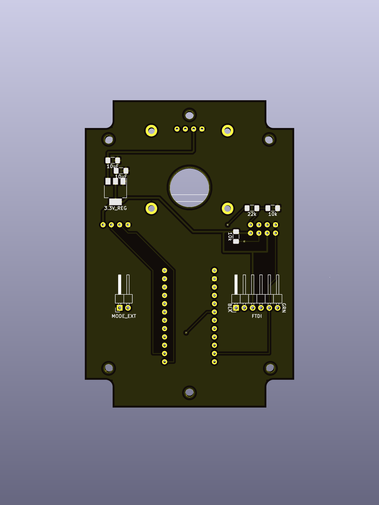
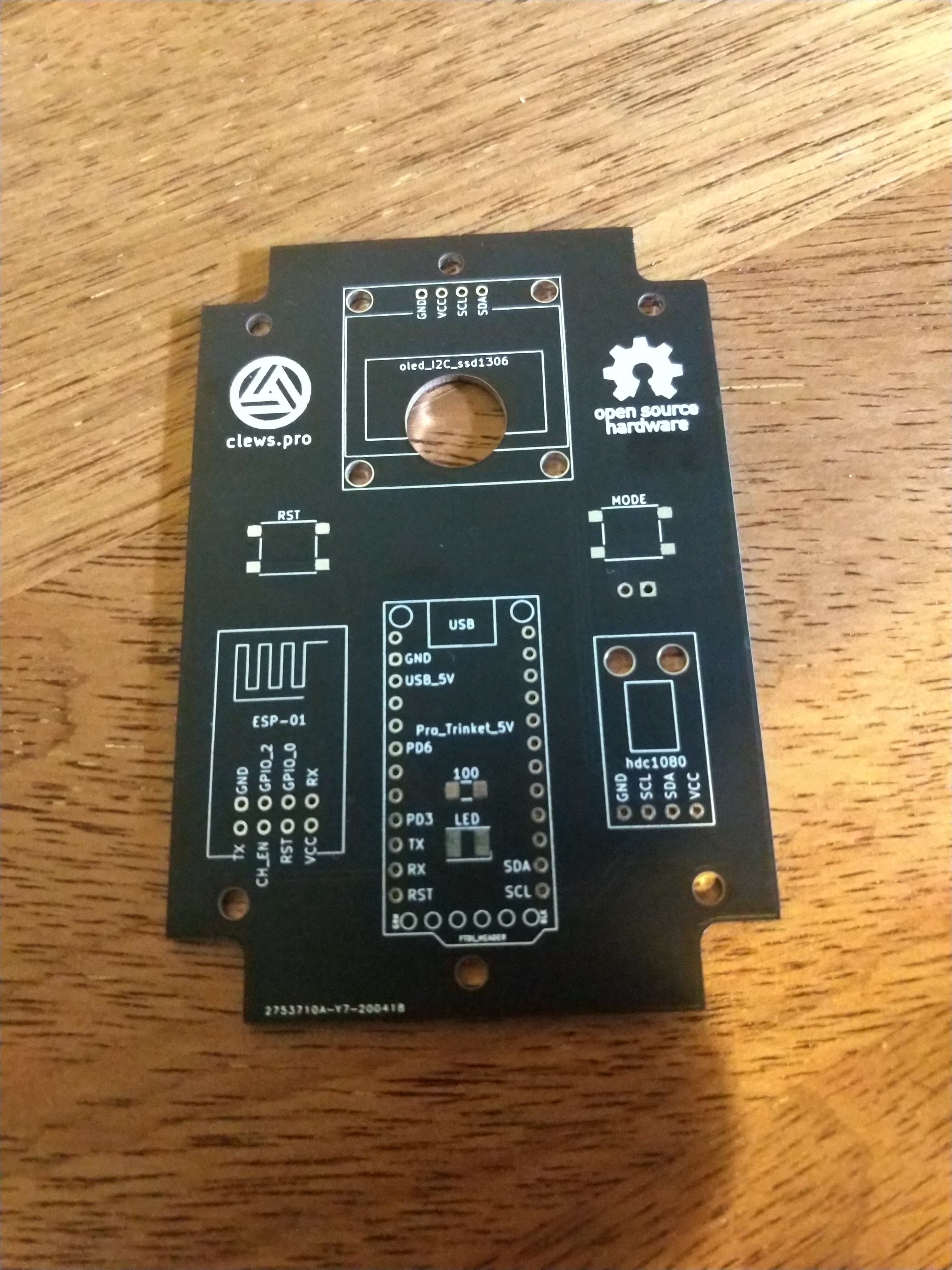
The schematic and PCB layouts were created with KiCad. Early iterations included a header for an FTDI serial adapter intended to facillitate programming of the ESP-01. This was removed from the final PCB iteration for simplicity.
A few component symbols and footprints were custom made:
Since the idea was to show off the Pro Trinket, I designed the PCB to suit an enclosure with a transparent lid that I had on hand. A panel mount micro-usb port on the side supplies power and also passes through data to allow re-programming without opening the case (for the Pro-Trinket at least - programming the ESP-01 requires removal of the module from the rest of the unit).
A push-button on top cycles through the different display modes. I included an LED on one of the analogue outputs which really doesn't serve much purpose except to add some extra bling. It is just set to pulse continuously. I located it so that it shines through the mounting hole on the Pro Trinket right under the Jolly-Wrencher symbol.
 |
 |
 |
 |
 |
 |
 |
 |
 |
 |
 |
 |
 |
 |
 |
 |
 |
 |
 |
 |
 |
 |
|