clewsy
A work-in-progress

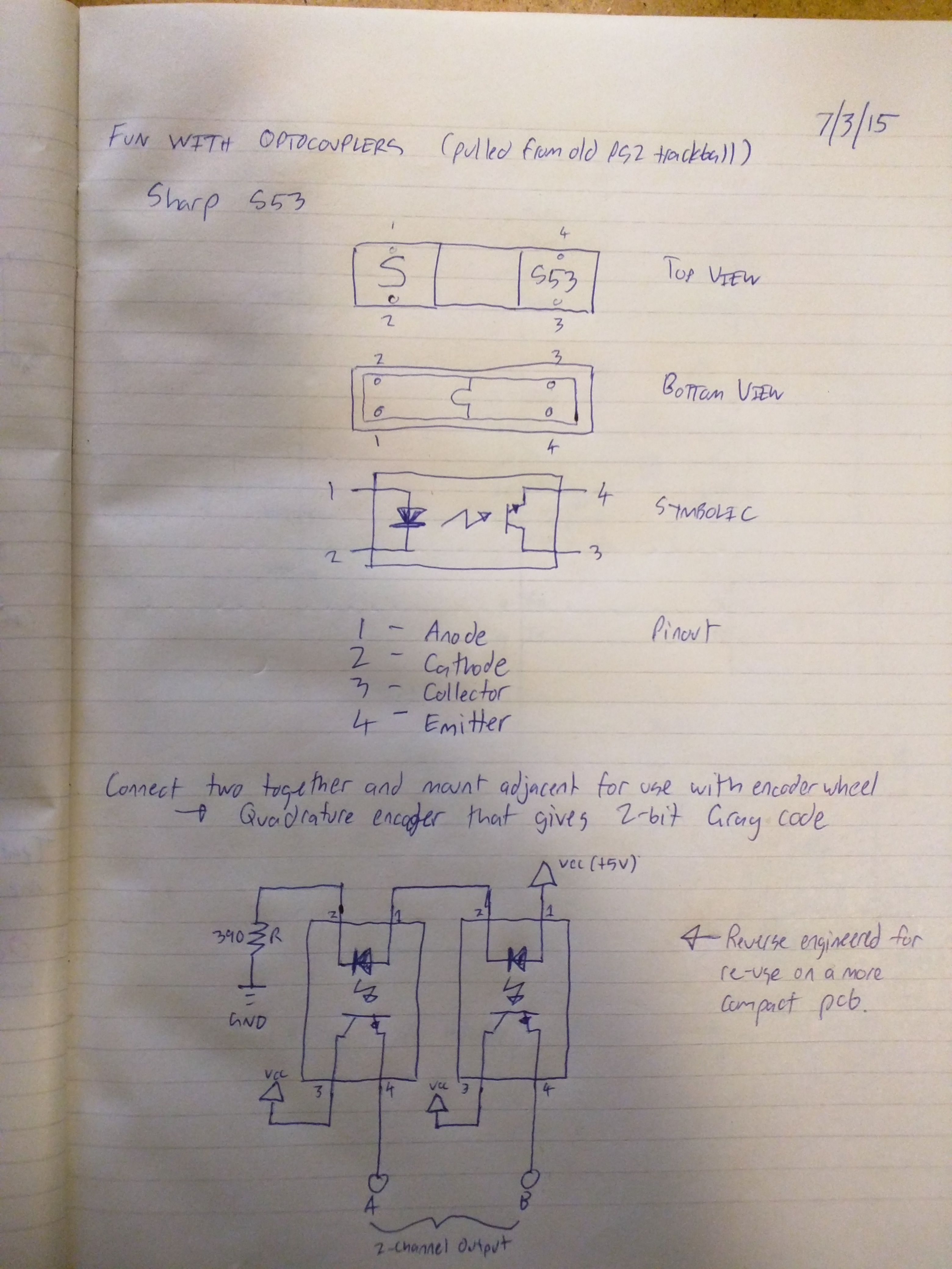
This project began as an experiment when I inexplicably decided to learn how an optical rotary encoder worked (FYI, 2-bit Gray code).
It transformed into a USM learning experience - specifically the HID protocol. Ultimately I ended up with a simple desk gadget that allows me to control the PC volume.
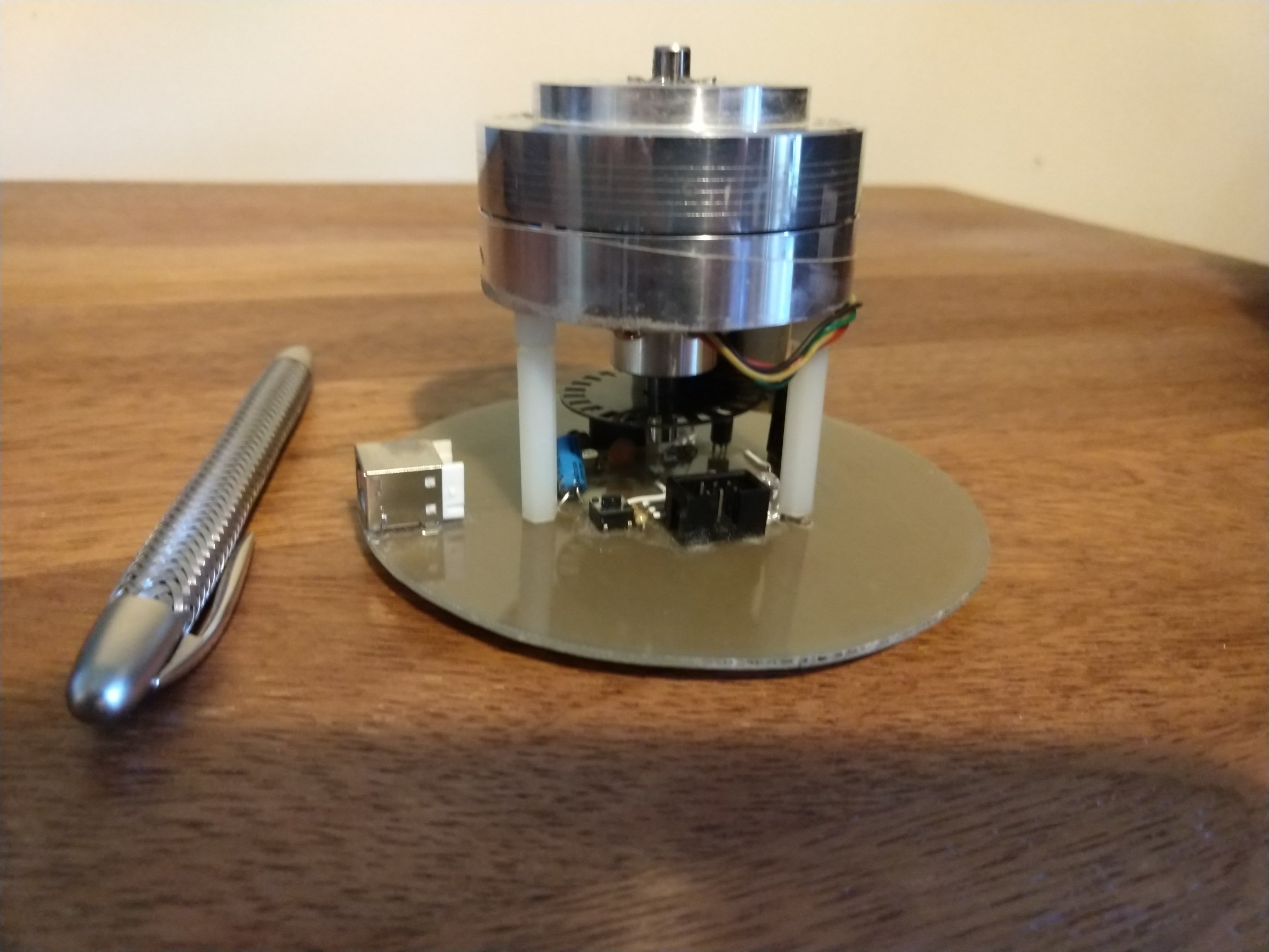
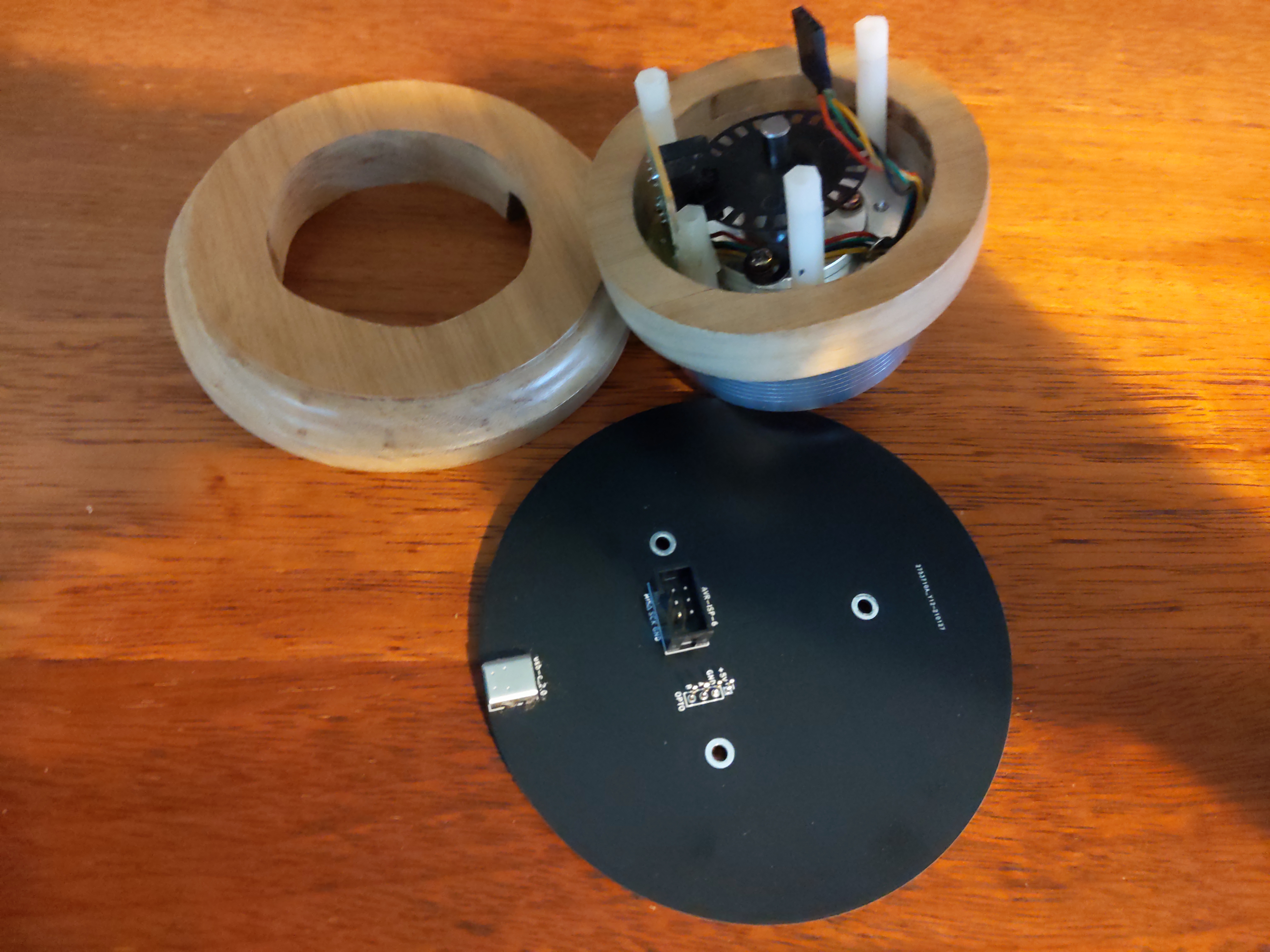
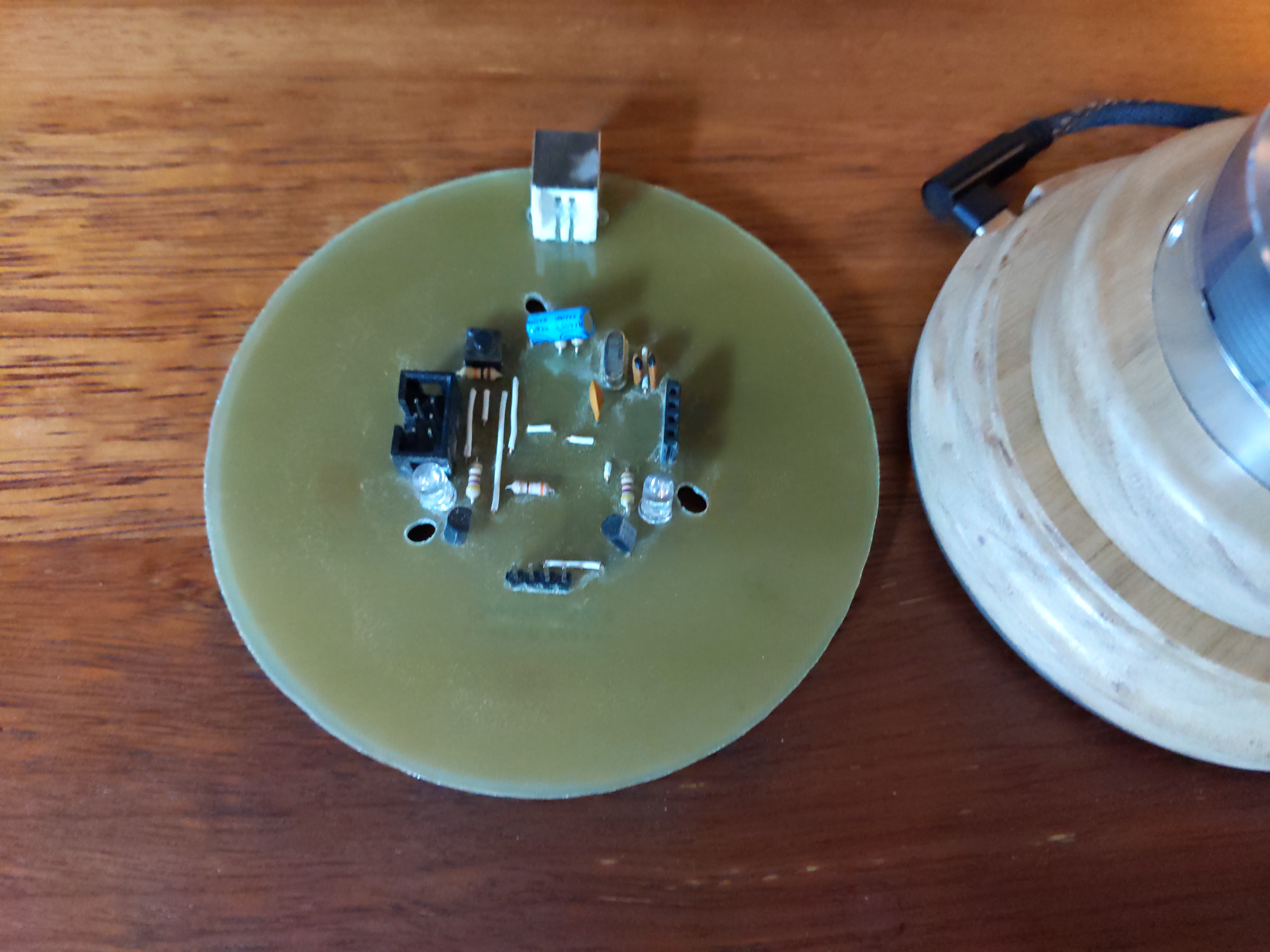
A salvaged optical encoder was used to detect rotation along with a reclaimed head drum from a VCR which was repurposed as a control knob. I very much like the smooth bearings combined with the heavy mass that let the drum spin forever.
Key concepts for the project were:
After some time (about six years!) of having this device in-use on my desk, I finally got sick of the simple (ugly) stained pine wood enclosure. With some scrap spotted gum and a router (using a Roman ogee and roundover bits) I made a slightly nicer enclosure for volcon.

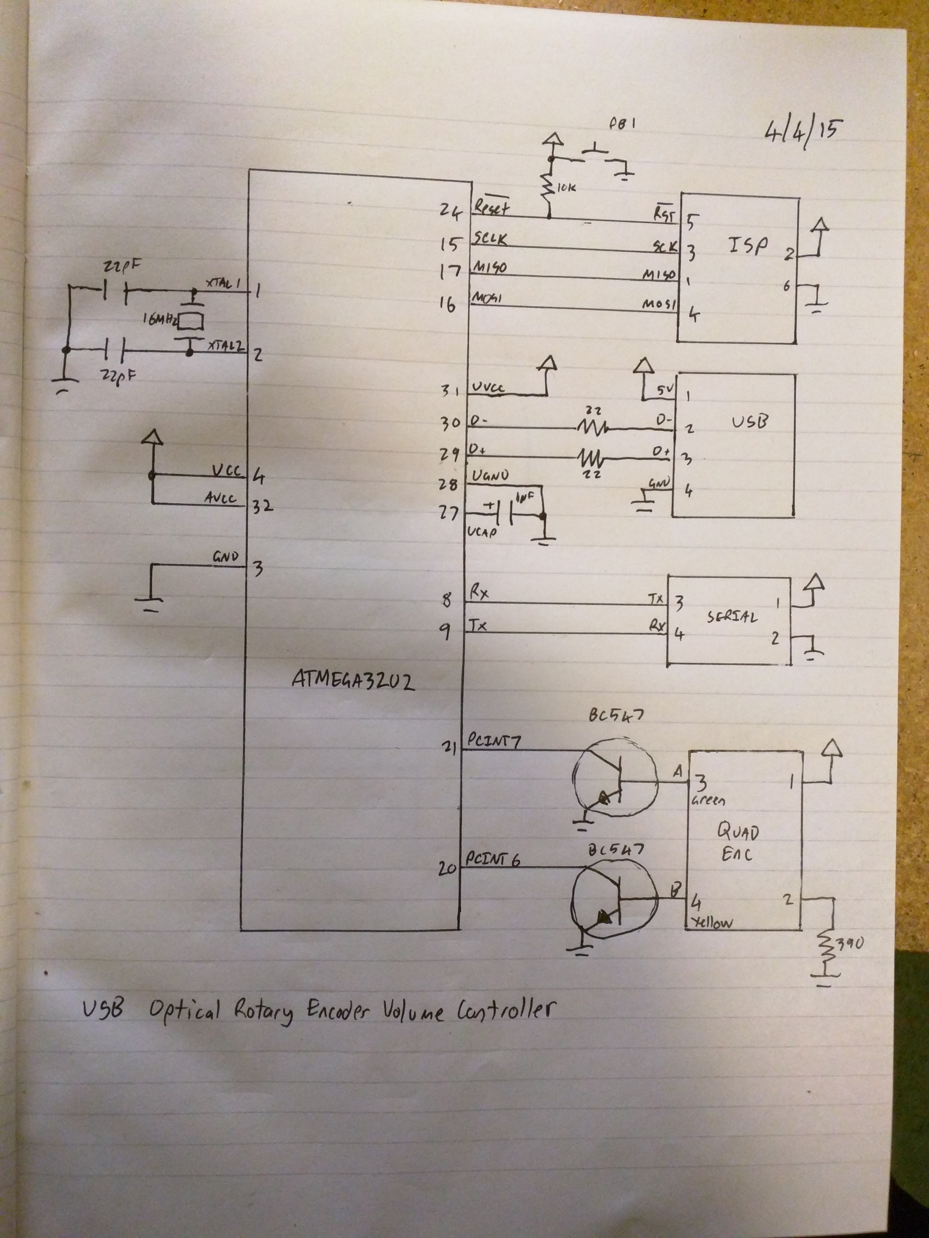
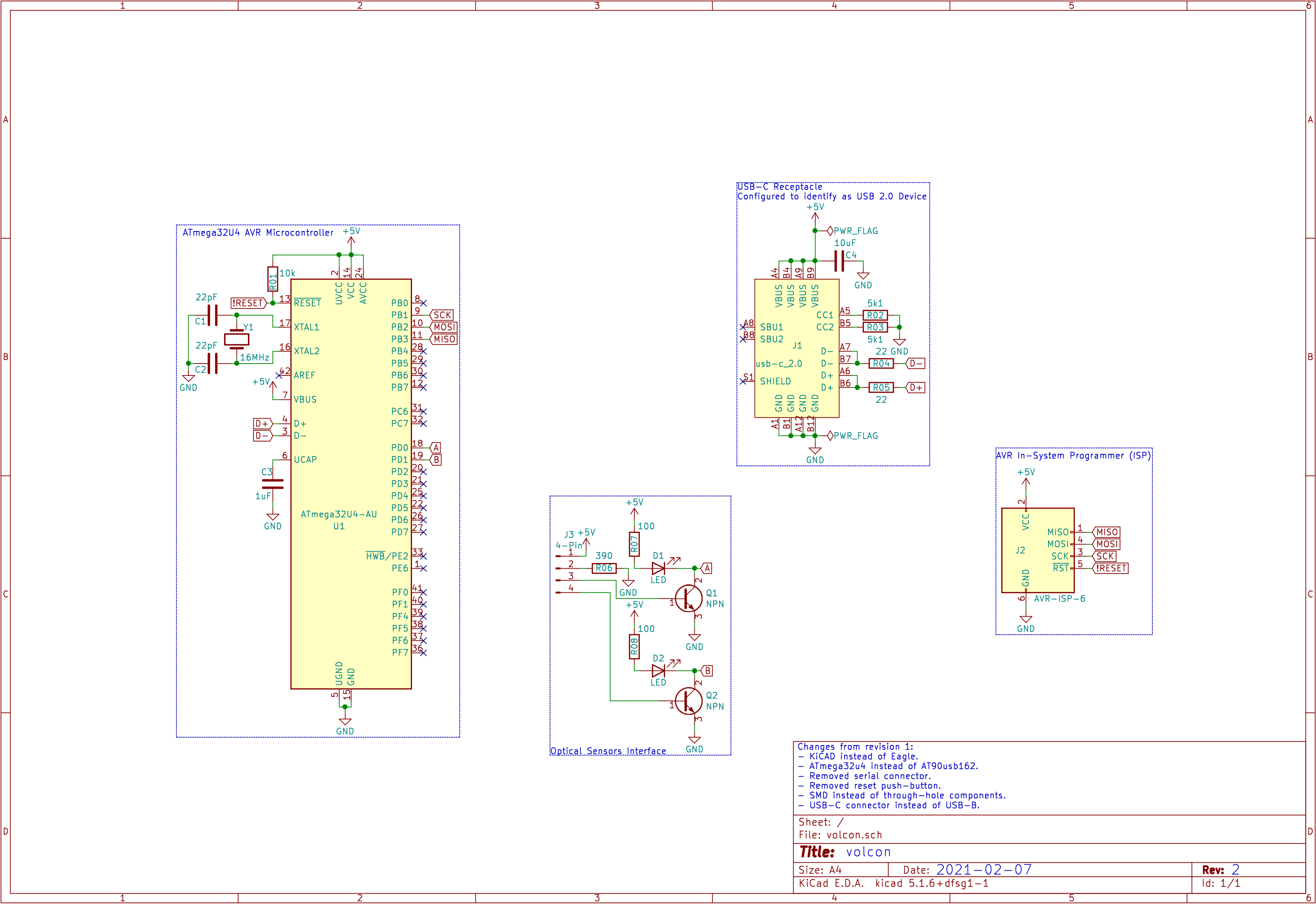
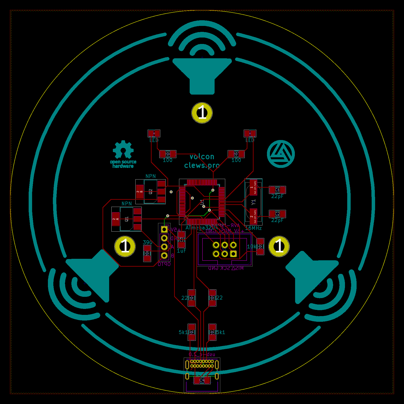
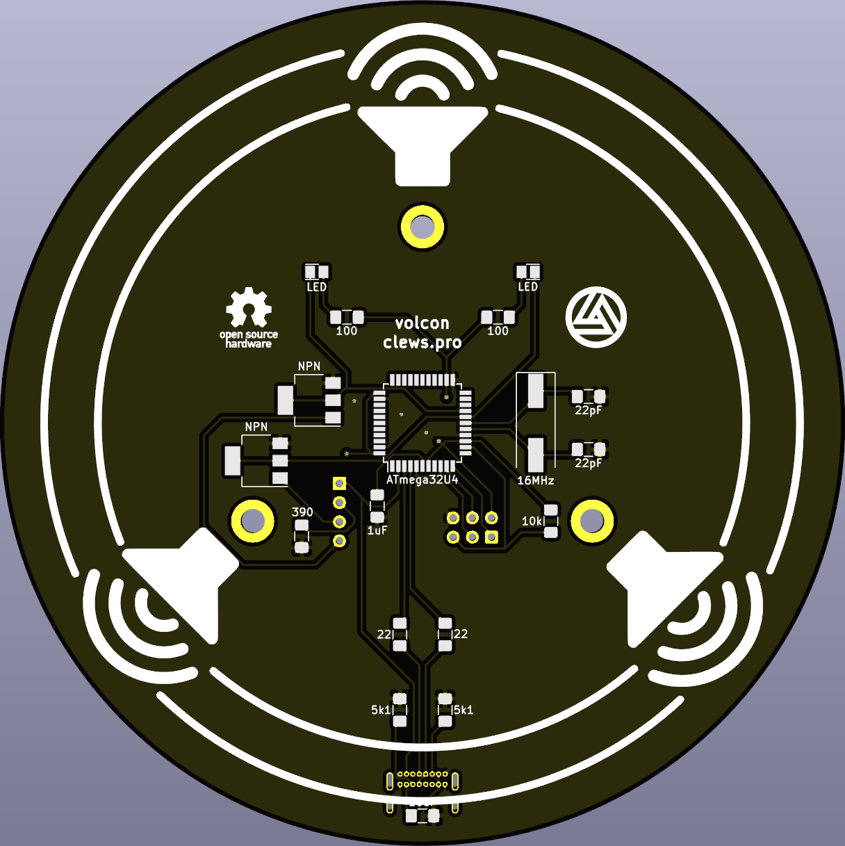
After even more time, I decided to do an overhaul. Revision 2 would use the same head drum, optical encoder sensors and wooden enclosure. The upgrades from revision 1 include:
The encoder consists of two optical sensor "beams" that are sequentially opened/interrupted by the holes within the encoder disk. The state of both the sensors can be represented as two bits.
Movement of the knob is simply determined by a change in the state of either of the two sensors. I.e. if either of the bits change, the device has rotated. The spacing of the sensors means only one of the bits will change at a time. Therefore, the direction of rotation is determined by comparing the current state of the two bits to the previous state of the two bits.
| Clockwise | 00 -> 10 -> 11 -> 01 -> 00 |
|---|---|
| Counter-Clockwise | 00 -> 01 -> 11 -> 10 -> 00 |
| # | Previous State | Current State | Rotation Direction | Delta |
|---|---|---|---|---|
| 0x0 | 00 | 00 | No movement. | 0 |
| 0x1 | 00 | 01 | Counter-clockwise. | -1 |
| 0x2 | 00 | 10 | Clockwise. | 1 |
| 0x3 | 00 | 11 | Not possible (error). | 0 |
| 0x4 | 01 | 00 | Clockwise. | 1 |
| 0x5 | 01 | 01 | No movement. | 0 |
| 0x6 | 01 | 10 | Not possible (error). | 0 |
| 0x7 | 01 | 11 | Counter-clockwise. | -1 |
| 0x8 | 10 | 00 | Counter-clockwise. | -1 |
| 0x9 | 10 | 01 | Not possible (error). | 0 |
| 0xA | 10 | 10 | No movement. | 0 |
| 0xB | 10 | 11 | Clockwise. | 1 |
| 0xC | 11 | 00 | Not possible (error). | 0 |
| 0xD | 11 | 01 | Clockwise. | 1 |
| 0xE | 11 | 10 | Counter-clockwise. | -1 |
| 0xF | 11 | 11 | No movement. | 0 |
Note in the table above, if the previous and current states are combined into a single 4-bit value in the order shown, this value is equal to #. So a 4-bit value (#) can be used to determine the direction of rotation.
In the code, any change in the state of either optical sensor triggers an interrupt function (see handle_opto() below) which updates the value of #, then uses a look-up table to determine the direction of movement (delta = -1, 0 or 1).
The look-up table is a one-dimensional array stored in eeprom. The element number corresponds to '#' and the element content corresponds to 'delta' in accordance with the table above.
void handle_opto(void)
{
// a_b is a 4-bit value that represents previous state (bits 3:2) and the current state (bits 1:0) of the encoder.
// Static to retain every time this function is called.
static uint8_t a_b = 0b0011;
// Encoder lookup table. Three versions of the table for various levels of "sensitivity".
static const int8_t enc_table [] PROGMEM = {0,-1,1,0,1,0,0,-1,-1,0,0,1,0,1,-1,0}; // Use every pulse.
//static const int8_t enc_table [] PROGMEM = {0,0,0,0,1,0,0,-1,-1,0,0,1,0,0,0,0}; // Use every second pulse.
//static const int8_t enc_table [] PROGMEM = {0,0,0,0,1,0,0,-1,0,0,0,0,0,0,0,0}; // Use every fourth pulse.
// "Remember" previous state of the channels.
a_b <<= 2;
// Read in the current state of the channels.
a_b |= (OPTO_PINS & OPTO_PIN_MASK);
// Look-up the desired volume delta (-1, 0 or 1) and send to the send_volume(delta) function.
send_volume(pgm_read_byte(&enc_table[a_b & 0x0f]));
}
 |
 |
 |
 |
 |
 |
 |
 |
 |
 |
 |
 |
 |
 |
 |
 |
 |
 |
 |
 |